Sequence Detector
The six specification questions, 24 interview framings solved end to end, interview-grade SystemVerilog, and the PPA trade-offs explained down to the transistor.
Read the complete handbook here. Code is selectable, tables scroll on small screens, and any diagram opens at full size when selected.
In this handbook
- Start here: how to use the handbook
- Cheat sheet
- 1. The problem & six spec questions
- 2. The thought process
- 3. All 24 interview framings
- 4. RTL coding practices
- 5. PPA down to the transistor
- A. Rapid fire, practice & glossary
Full contents — jump to any section
How to use this handbook
This handbook covers one interview topic end to end: detecting a bit pattern in a serial stream. It follows the order of a real interview. First you pin down the spec, then you apply a method, then you write RTL, and finally you defend your choices on power, performance and area.
First read. Chapter 1 covers the problem and the six questions to ask, and Chapter 2 the one rule that builds every detector. After that, work through the framings in Chapter 3 in any order; each one is self-contained. Chapter 4 covers coding discipline and Chapter 5 covers PPA down to the transistor. That depth is what separates “correct” from “hire”.
The night before. Read the cheat sheet below, every Say this in the interview box, and the rapid-fire questions in Appendix A.
Callouts. Four kinds of box appear throughout:
- Say this in the interview: a sentence worth saying aloud.
- Trap: a mistake that loses points.
- Circuit view: the transistor-level reason behind a trade-off.
- Tip: a shortcut.
Conventions
| Item | Convention |
|---|---|
| Bit order | Patterns are written first bit on the left: 1011 means the 1 arrives first. In RTL, pattern[N-1] is the first bit expected. |
| Arc labels | Mealy arcs read din/detect. Moore arcs read din, and the output is written inside the state. |
| State names | Each state is named after the part of the pattern already matched: S10 means “the last bits were 1 then 0”. IDLE means nothing is matched. |
| Timing | Cycle k is the clock period in which bit k is on din. Mealy outputs appear in that cycle; Moore and registered outputs one cycle later. |
| Reset | Asynchronous and active low (rst_n) unless a section says otherwise. |
| Area unit | GE = gate equivalent, the area of one 2-input NAND (4 transistors). |
The code
Every listing in this book is printed from a real file in 01_sequence_detector/. Each file is compile-checked with slang (via pyslang) and cross-checked against a behavioural model on thousands of random streams. The files all start with `timescale 1ns/1ps; the listings skip that line.
| Path | Contents |
|---|---|
seq_det_mealy.sv, seq_det_moore.sv, seq_det_shift.sv |
the three core detectors (Chapter 1, F6) |
tb_seq_det.sv |
self-checking testbench for the core detectors (F20) |
variants/*.sv |
one file per framing in Chapter 3 |
handbook/ |
the original handbook sources, including snippets.sv and verify_models.py |
To run the testbench on EDA Playground, paste the three core files into design.sv and tb_seq_det.sv into testbench.sv, then pick any SystemVerilog simulator.
Cheat sheet
The rule
The state is the longest prefix of the pattern that the bits seen so far end with. For the next state, append the new bit and apply the rule again. After a full match, an overlapping detector goes to the pattern’s border: the longest proper prefix that is also a suffix.
Ask before you draw
- Overlapping or non-overlapping?
- Mealy (same cycle) or Moore (one cycle later)?
- One-cycle pulse or a level?
- Which bit arrives first?
- Reset: synchronous or asynchronous, active high or low?
- Input valid? Programmable pattern? Maximum length?
Size it (N-bit pattern)
| Mealy | Moore | |
|---|---|---|
| States | N | N + 1 |
| Binary flops | ⌈log₂N⌉ | ⌈log₂(N+1)⌉ |
| One-hot flops | N | N + 1 |
A shift register needs N − 1 flops plus an N-bit compare (Mealy timing), or N flops (Moore timing).
Numbers to remember (Chapter 5)
| Quantity | Value |
|---|---|
| Area, Mealy, binary | 19 GE |
| Area, Moore, binary | 29 GE |
| Area, Moore, one-hot | 42 GE |
| Area, Shift + compare, fill counter | 36 GE |
| Area, Shift + compare, reset trick | 21 GE |
| State-bit toggles per cycle: binary Mealy, one-hot Moore, shift register | 0.88, 1.44, 1.50 |
| 64-input AND: best tree vs two giant gates | 25 τ vs 43 τ |
| Synchronizer MTBF: one flop vs two flops | 1.6 s vs 12 billion years |
Pick an implementation
| Situation | Choice |
|---|---|
| Short fixed pattern, area matters | binary FSM |
| Output leaves the block | Moore or registered Mealy |
| FPGA, or highest clock rate | one-hot FSM |
| Long, programmable, several, masked | shift register + comparator |
| Very long pattern at high clock | pipelined comparator |
| Run of identical bits | counter |
| W bits per clock | W comparators on a sliding window |
Top traps
- For 1011,
S101on 0 goes toS10, notIDLE, andS1on 1 stays inS1. - The Moore detect state needs its own arcs: for 1011, to
S1on a 1 and toS10on a 0. - A shift register can fire right after reset (pattern
0011, stream11), so mask it until the history is real. - A missing
defaultorelseinalways_combinfers a latch. - A Mealy output is a combinational path from
din. Register it at block boundaries. - Overlap only matters when the pattern has a border:
110has none.
Say this
- “I’ll name each state by what it has matched, and for every wrong bit ask what the longest prefix is that I still hold.”
- “Mealy saves a state and a cycle. If
detectleaves the block, I’ll register it.” - “An FSM is a feedback loop, so it can’t be pipelined. A comparator is feed-forward, so it can.”
Chapter 1The problem and the six spec questions
A sequence detector watches a serial stream, one bit per clock, and raises detect when the most recent N bits equal a pattern. It is string matching in hardware: one new character every clock, and very little memory. The design only has to remember how much of the pattern it has matched so far. That memory is the state. Every variant of the question is really about how you store that memory (FSM states or a shift register) and when the answer comes out.
Six questions define the design. Interviewers often leave them open on purpose, and asking them is part of the score.
| # | Question | Default if the answer is “your choice” |
|---|---|---|
| 1 | Overlapping or non-overlapping matches? | Overlapping |
| 2 | Mealy timing (same cycle) or Moore timing (next cycle)? | Mealy |
| 3 | A one-cycle pulse per match, or a level? | Pulse |
| 4 | Which bit is transmitted first? | The leftmost (MSB first) |
| 5 | Reset: synchronous or asynchronous, and which polarity? | Asynchronous, active low |
| 6 | Is there an input valid? Is the pattern fixed or programmable, and how long can it be? | No valid, fixed 4-bit pattern |
State your defaults out loud when you choose them. The rest of this chapter answers each question with the design change it causes.
1.1 Overlapping or non-overlapping
In 1011011, an overlapping detector fires twice, because the matches on bits 1–4 and 4–7 share bit 4. A non-overlapping detector fires once, because bit 4 was already used. In the FSM, the difference is exactly one arc: the one taken after a match.
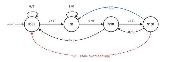
din/detect. After a match, the overlapping machine keeps the trailing 1 and goes to S1 (blue). The non-overlapping machine starts over at IDLE (dashed red).After a full match, an overlapping FSM moves to the state for the pattern’s border, the longest proper prefix that is also a suffix. The border of 1011 is 1, so it moves to S1. A non-overlapping FSM always restarts at IDLE, or at a state that behaves exactly like it. Chapter 2 shows how to find the border of any pattern in seconds.
// Serial detector for the pattern 1011 (the first bit received is the MSB).
// Mealy: detect depends on the state AND din, so it is high in the same cycle
// that the final '1' is on din.
module seq_det_mealy #(
  parameter bit OVERLAP = 1'b1    // 1: "1011011" gives two hits, 0: one hit
) (
  input  logic clk,
  input  logic rst_n,             // asynchronous, active low
  input  logic din,
  output logic detect
);

  // Each state is named after the part of 1011 matched so far
  typedef enum logic [1:0] {
    IDLE = 2'd0,
    S1   = 2'd1,
    S10  = 2'd2,
    S101 = 2'd3
  } state_t;

  state_t state, state_nxt;

  always_ff @(posedge clk or negedge rst_n) begin
    if (!rst_n) state <= IDLE;
    else        state <= state_nxt;
  end

  always_comb begin
    case (state)
      IDLE   : state_nxt = din ? S1   : IDLE;
      S1     : state_nxt = din ? S1   : S10;    // "11" still ends in "1"
      S10    : state_nxt = din ? S101 : IDLE;
      S101   : state_nxt = din ? (OVERLAP ? S1 : IDLE)
                               : S10;           // "1010" still ends in "10"
      default: state_nxt = IDLE;
    endcase
  end

  assign detect = (state == S101) && din;

endmoduleOVERLAP term on the S101 row.PPA. The two behaviours cost the same, because the parameter changes a single next-state term. In the shift-register version (F6), non-overlap costs one extra condition: clear the fill counter on a hit.
1.2 Mealy or Moore timing
A Mealy output depends on the state and the input, so detect is high in the same cycle the last bit is on din. A Moore output depends only on the state, so it is high one cycle later. Moore therefore needs one extra state that means “just matched”.
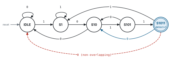
S1011 is the only state with detect = 1. Its arcs are derived like any other state’s: after a 1 the bits end in 1 (S1); after a 0 they end in 10 (S10).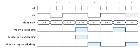
// Serial detector for the pattern 1011 (the first bit received is the MSB).
// Moore: detect depends only on the state, so it is high in the cycle AFTER
// the final '1' was sampled.
module seq_det_moore #(
  parameter bit OVERLAP = 1'b1
) (
  input  logic clk,
  input  logic rst_n,             // asynchronous, active low
  input  logic din,
  output logic detect
);

  typedef enum logic [2:0] {
    IDLE  = 3'd0,
    S1    = 3'd1,
    S10   = 3'd2,
    S101  = 3'd3,
    S1011 = 3'd4                  // full match: the only state with detect = 1
  } state_t;

  state_t state, state_nxt;

  always_ff @(posedge clk or negedge rst_n) begin
    if (!rst_n) state <= IDLE;
    else        state <= state_nxt;
  end

  always_comb begin
    case (state)
      IDLE   : state_nxt = din ? S1    : IDLE;
      S1     : state_nxt = din ? S1    : S10;
      S10    : state_nxt = din ? S101  : IDLE;
      S101   : state_nxt = din ? S1011 : S10;
      S1011  : state_nxt = din ? S1    : (OVERLAP ? S10 : IDLE);  // "10110" ends in "10"
      default: state_nxt = IDLE;     // the 3 unused encodings recover here
    endcase
  end

  assign detect = (state == S1011);

endmodule
The deeper difference is the timing path. A Mealy machine has a purely combinational path from din to detect (Figure 1.4). Suppose din comes from a flop in another block and detect goes to a flop in a third. Then one path has to fit inside both blocks’ timing budgets, and any glitch on din or on the state bits travels straight through to detect.
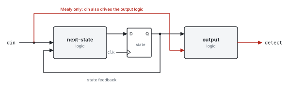
din reaches detect through combinational logic.At a block boundary, the usual answer is a registered Mealy: put a flop on the Mealy output. Its timing is identical to Moore, and the output comes straight off a flop, so it is glitch-free and costs only clock-to-Q. For 1011 it needs the same three flops as Moore.
// Mealy detector for 1011 with a registered output. detect rises one cycle
// after the final '1' (the same timing as Moore) but comes straight off a
// flop, so it is glitch-free. Cost: 2 state flops + 1 output flop.
module seq_det_mealy_reg #(
  parameter bit OVERLAP = 1'b1
) (
  input  logic clk,
  input  logic rst_n,             // asynchronous, active low
  input  logic din,
  output logic detect
);

  logic hit;                      // combinational Mealy output

  seq_det_mealy #(.OVERLAP(OVERLAP)) u_core (
    .clk(clk), .rst_n(rst_n), .din(din), .detect(hit));

  always_ff @(posedge clk or negedge rst_n) begin
    if (!rst_n) detect <= 1'b0;
    else        detect <= hit;
  end

endmodule“Mealy saves a state and a cycle of latency, but it leaves a combinational path from din to detect. If detect leaves this block, I’d register it. That gives Moore timing with a glitch-free output, and costs one flop.”
1.3 Pulse or level
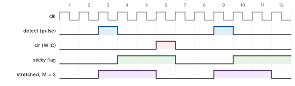
The default is a one-cycle pulse per match. Two other output forms come up. A sticky flag stays set until software clears it, like a status bit. A stretched pulse is held for M cycles so that a slower clock domain, or an LED, can see it.
// Turns a one-cycle detect pulse into a level that stays high until software
// clears it (write-1-to-clear). A pulse in the same cycle as a clear wins,
// so no match is ever lost.
module pulse_to_sticky (
  input  logic clk,
  input  logic rst_n,             // asynchronous, active low
  input  logic pulse,             // e.g. detect from any seq_det_* module
  input  logic clr,               // write-1-to-clear strobe
  output logic flag
);

  always_ff @(posedge clk or negedge rst_n) begin
    if (!rst_n)     flag <= 1'b0;
    else if (pulse) flag <= 1'b1;
    else if (clr)   flag <= 1'b0;
  end

endmodule// Stretches a one-cycle pulse to M cycles (M >= 2), for example so that a
// slower clock domain or an LED can see it. A new pulse restarts the stretch.
module pulse_stretch #(
parameter int M = 4
) (
input logic clk,
input logic rst_n, // asynchronous, active low
input logic pulse,
output logic level
);
localparam int CW = $clog2(M);
localparam logic [CW-1:0] HOLD = CW'(M - 1);
logic [CW-1:0] left; // cycles still to hold after this one
always_ff @(posedge clk or negedge rst_n) begin
if (!rst_n) left <= '0;
else if (pulse) left <= HOLD;
else if (left != '0) left <= left - 1'b1;
end
assign level = pulse || (left != '0);
endmoduleCorner case to raise yourself: a match can arrive in the same cycle as the clear. If the set wins, no match is ever lost, which is the usual rule for status registers.
PPA. A sticky flag costs one flop. A stretch costs ⌈log₂M⌉ flops and a decrementer. The stretched level output is combinational from pulse, so register it before it crosses a clock domain.
1.4 Bit order
“Detect 1011” is ambiguous until you know which bit goes on the wire first. On an LSB-first link, the value 1011 arrives as 1, 1, 0, 1, so the detector has to look for 1101. Nothing else changes: reverse the pattern and reuse the MSB-first design.

// LSB-first link: the pattern's LSB is transmitted first, so detect the
// bit-reversed pattern with the unchanged MSB-first detector.
module seq_det_lsb #(
  parameter int           N       = 4,
  parameter logic [N-1:0] PATTERN = 4'b1011    // as written in the spec
) (
  input  logic clk,
  input  logic rst_n,             // asynchronous, active low
  input  logic din,
  output logic detect
);

  localparam logic [N-1:0] ARRIVAL = {<<{PATTERN}};   // 1011 -> 1101

  seq_det_shift #(.N(N)) u_det (
    .clk(clk), .rst_n(rst_n), .pattern(ARRIVAL), .din(din), .detect(detect));

endmodule
{<<{PATTERN}} is the SystemVerilog streaming operator; with the default slice size of one bit, it reverses the vector.PPA. Nothing: bit reversal is just wiring. The trap here is purely functional.
1.5 Reset
There are four reset styles, and all are legal: asynchronous or synchronous, each active low or active high. The interviewer wants to hear that you know how they differ, and that you have a default.
always_ff @(posedge clk or negedge rst_n) begin   // asynchronous, active low
  if (!rst_n) q_an <= 1'b0;
  else        q_an <= d;
endalways_ff @(posedge clk) begin // synchronous, active high
if (rst) q_sh <= 1'b0;
else q_sh <= d;
end| Asynchronous reset | Synchronous reset | |
|---|---|---|
| Needs a running clock | No: it resets immediately | Yes: it waits for a clock edge |
| Where the logic sits | Inside the flop: NAND gates in its feedback loops (Section 5.1) | In front of the flop, in the D path |
| Cost | A larger flop: about 4 more transistors in a transmission-gate design | A plain flop plus an AND gate, which synthesis often merges into the logic |
| Timing | Release must meet recovery and removal times, so synchronize the deassertion | Behaves like data: ordinary setup and hold, but adds a gate to the D path |
| Glitches on the reset line | Reset the flop | Filtered out by the clock |
Asynchronous reset has one hazard: releasing it close to a clock edge can make a flop metastable, or let some flops leave reset a cycle before others. The standard cure is asynchronous assert, synchronous deassert. Reset goes low immediately, but its release is re-timed by two flops in the destination clock domain.
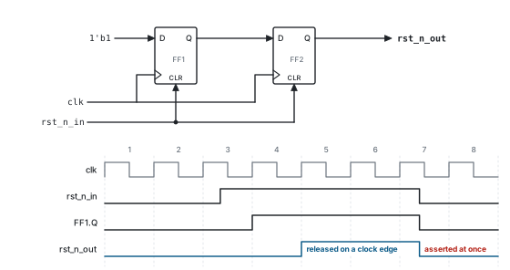
rst_n_out falls at once but rises only on a clock edge, two edges after rst_n_in is released.// Reset synchronizer: asynchronous assert, synchronous deassert. rst_n_out
// falls as soon as rst_n_in falls, but rises only on a clock edge, STAGES
// edges after rst_n_in rises, so no flop sees reset release near its edge.
module reset_sync #(
parameter int STAGES = 2 // >= 2; more stages = higher MTBF
) (
input logic clk,
input logic rst_n_in, // raw asynchronous reset, active low
output logic rst_n_out // reset for everything in the clk domain
);
logic [STAGES-1:0] sync;
always_ff @(posedge clk or negedge rst_n_in) begin
if (!rst_n_in) sync <= '0;
else sync <= {sync[STAGES-2:0], 1'b1};
end
assign rst_n_out = sync[STAGES-1];
endmoduleWhat to reset. Reset the control state: the FSM state, counters and valid flags. Datapath registers such as a shift register’s history can skip reset if something else masks them until they hold real data (F6). That saves area and lightens the reset tree (Section 5.4).
Why active low? Reset is conventionally active low for three reasons. A reset line held low during power-up is naturally asserted while the supply ramps. Several open-drain sources can share one reset wire, and any of them can pull it low. And most IP expects rst_n. FPGA vendors generally prefer synchronous resets, applied only where they are needed.
1.6 The extras: valid, programmable, long
The last question opens up the harder framings. Each of these gets its own worked solution in Chapter 3.
| If the answer is… | The design becomes… | See |
|---|---|---|
| Bits come with a valid, and there are bubbles | The state advances only on valid, and detect is qualified by valid |
F11 |
| The pattern comes from a register | Shift register + comparator; an FSM is no longer practical | F7 |
| Some pattern bits are don’t-care, or bit errors must be tolerated | A care mask, or XOR plus popcount | F10 |
| The pattern is 32 or 64 bits | A pipelined comparator | F8 |
| Several patterns, report which one matched | A shared history with one comparator per pattern | F9 |
| W bits arrive per clock | W comparators on a sliding window | F12 |
Chapter 2The thought process
2.1 One rule builds every detector
The state is the longest prefix of the pattern that the bits received so far end with. To find the next state, append the new bit and apply the rule again.
Why this is enough. Any future match that overlaps the bits already received has to start inside the part of the pattern matched so far. The longest matched prefix holds every shorter possibility, because each shorter candidate is a prefix of the pattern that the longest one also ends with. Older bits can never matter again. This is the automaton behind the Knuth–Morris–Pratt string-matching algorithm, and it is also the smallest possible machine for “the input ends in P”. No correct detector can have fewer states.
How to apply it when a wrong bit arrives. Don’t throw everything away. Line the pattern up under the bits you now have, and try the longest prefix first, then shorter ones. The first prefix that matches the end of your bits is the next state.
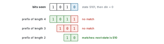
S101 on a 0. The bits now end in 1010. Neither the length-4 nor the length-3 prefix fits, but the length-2 prefix 10 does, so the next state is S10, not IDLE.2.2 The whiteboard routine
Say each step aloud as you do it. Interviewers score the reasoning as much as the answer.
- Clarify the six questions from Chapter 1. “Before I draw: overlapping? Mealy or Moore? One-cycle pulse?”
- Name the states by what they have matched:
IDLE,S1,S10,S101, plusS1011for Moore. “Mealy needs N states; Moore needs N + 1, because it needs a state that means ‘just matched’.” - Draw the happy path:
IDLE → S1 → S10 → S101 →match. - Fill every fallback arc using the rule. Most candidates lose the question here, so work it as a table (Section 2.3).
- Decide overlap. It changes only the arc taken after a match (Section 2.4).
- Dry-run the trap streams (Section 2.6). “Let me check that 101011 still fires, because that exercises
S101on a 0.” - Write the RTL as three blocks: state register, next-state logic, output logic (Chapter 4).
- Offer verification and PPA before you are asked (F20, Chapter 5).
2.3 Deriving 1011
Every state has two arcs, one per input value. A 4-state Mealy machine therefore has 8 arcs, and a 5-state Moore machine has 10. If your diagram has fewer, an arc is missing.
| State (matched) | din |
Bits now end in | Longest prefix of 1011 | Next state | Mealy detect |
|---|---|---|---|---|---|
IDLE |
0 | 0 | none | IDLE |
0 |
IDLE |
1 | 1 | 1 | S1 |
0 |
S1 |
0 | 10 | 10 | S10 |
0 |
S1 |
1 | 11 | 1 | S1 |
0 |
S10 |
0 | 100 | none | IDLE |
0 |
S10 |
1 | 101 | 101 | S101 |
0 |
S101 |
0 | 1010 | 10 | S10 |
0 |
S101 |
1 | 1011 | full match, then its border 1 |
S1 (overlap) / IDLE |
1 |
S1011 (Moore) |
0 | 10110 | 10 | S10 (overlap) / IDLE |
– |
S1011 (Moore) |
1 | 10111 | 1 | S1 |
– |
The rows in bold are the ones people get wrong. S1 on a 1 stays in S1, because “11” still ends in “1”. S101 on a 0 goes to S10, because “1010” still ends in “10”.
2.4 Shortcut: after a match, go to the border
The border of a pattern is its longest proper prefix that is also a suffix. After a match, an overlapping detector is in the border’s state, and a non-overlapping one is in IDLE.
| Pattern | Border | Overlapping: after a match | Non-overlapping: after a match |
|---|---|---|---|
| 1011 | 1 |
S1 |
IDLE |
| 1101 | 1 |
S1 |
IDLE |
| 1001 | 1 |
S1 |
IDLE |
| 1010 | 10 |
S10 |
IDLE |
| 0110 | 0 |
S0 |
IDLE |
| 1111 | 111 |
S111 |
IDLE |
| 1110 | none | IDLE |
IDLE: the two machines are identical |
| 110 | none | IDLE |
IDLE: the two machines are identical |
“This pattern has no border, so overlapping and non-overlapping detection are the same machine.” Saying this shows you understand the concept rather than a recipe.
2.5 Worked tables
These are the overlapping Mealy machines for the patterns interviewers use most. The entry “match” means detect = 1, and the state after it is the border’s state. Every table was generated from the rule above and checked by program.
1101 (border 1)
| State | on 0 | on 1 |
|---|---|---|
IDLE |
IDLE |
S1 |
S1 |
IDLE |
S11 |
S11 |
S110 |
S11 |
S110 |
IDLE |
match, S1 |
Traps: 11101 fires at bit 5 (tests S11 on a 1). 1101101 fires at 4 and 7.
1001 (border 1)
| State | on 0 | on 1 |
|---|---|---|
IDLE |
IDLE |
S1 |
S1 |
S10 |
S1 |
S10 |
S100 |
S1 |
S100 |
IDLE |
match, S1 |
Traps: 101001 fires at bit 6 (tests S10 on a 1). 1001001 fires at 4 and 7.
1010 (border 10)
| State | on 0 | on 1 |
|---|---|---|
IDLE |
IDLE |
S1 |
S1 |
S10 |
S1 |
S10 |
IDLE |
S101 |
S101 |
match, S10 |
S1 |
Traps: 101010 fires at 4 and 6. 10110 never fires (tests S101 on a 1).
1110 (no border)
| State | on 0 | on 1 |
|---|---|---|
IDLE |
IDLE |
S1 |
S1 |
IDLE |
S11 |
S11 |
IDLE |
S111 |
S111 |
match, IDLE |
S111 |
Trap: 11110 fires at bit 5 (tests S111 on a 1).
0110 (border 0)
| State | on 0 | on 1 |
|---|---|---|
IDLE |
S0 |
IDLE |
S0 |
S0 |
S01 |
S01 |
S0 |
S011 |
S011 |
match, S0 |
IDLE |
Traps: 00110 fires at bit 5 (tests S0 on a 0). 0110110 fires at 4 and 7.
2.6 Dry runs that catch mistakes
Before writing RTL, push each trap stream through your table. Each stream is chosen to exercise a different arc of the 1011 detector.
| Stream | Overlapping hits | Non-overlapping hits | Arc it tests |
|---|---|---|---|
101011 |
bit 6 | bit 6 | S101 on a 0 goes to S10 |
11011 |
bit 5 | bit 5 | S1 on a 1 stays in S1 |
1011011 |
bits 4, 7 | bit 4 | the arc after a match (border) |
1011011011 |
bits 4, 7, 10 | bits 4, 10 | non-overlap resumes correctly |
The most common wrong design sends every mismatch back to IDLE. It still passes 1011, so it looks right, but it misses the hit in both 101011 and 11011. Always dry-run at least one stream that returns through each fallback arc.
2.7 A 45-minute plan
| Minutes | What you do |
|---|---|
| 0–3 | Ask the six questions and state your defaults |
| 3–10 | Draw the states, the happy path and the fallback arcs, then dry-run a trap stream |
| 10–20 | Write the RTL in three blocks and explain each one |
| 20–25 | Draw the waveform for one trap stream |
| 25–35 | Discuss PPA: Mealy vs Moore, state encoding, FSM vs shift register |
| 35–45 | Take the follow-ups: programmable pattern, long patterns, W bits per clock, verification |
Chapter 324 framings, solved
The same question arrives in many forms. Each framing below follows one template: how it is asked, what it really tests, the solution (with a diagram and RTL), the PPA view, and the follow-ups to expect. F1–F16 are the classic framings, and F17–F24 are the variations that separate strong candidates.
F1 Detect 1011, overlapping
- Design an FSM that detects 1011 in a serial bit stream.
- Draw the state diagram, then write the RTL.
Tests: the method of Chapter 2, the fallback arcs, and clean three-block RTL.
Solution. Use the Mealy machine of Figure 1.1 and Listing 1.1: four states in two flops. With the encoding used in the RTL (IDLE = 00, S1 = 01, S10 = 10, S101 = 11), the logic collapses to three equations:
s0'    = din
s1'    = s0 & ~din  |  s1 & ~s0 & din
detect = s1 & s0 & din
So s0 is just the previous input bit, a gift of the encoding. Point it out: it shows you look at the logic, not only at the diagram.
PPA. About 19 GE: two resettable flops (12 GE) plus about 7 GE of logic (the area table in Section 5.1). The critical path is clock-to-Q, one AND-OR level, then setup.
Follow-ups. Why four states? One per proper prefix of the pattern: “”, 1, 10, 101. What’s the minimum number of flops? ⌈log₂4⌉ = 2. Why does S1 loop on a 1? Because “11” still ends in “1”.
F2 Non-overlapping
- Now make it non-overlapping.
- Each bit may belong to at most one match.
Tests: whether you know that only the post-match arc changes.
Solution. After a match, go to IDLE instead of the border’s state: the dashed arcs in Figure 1.1 and Figure 1.2, or OVERLAP = 0 in the listings. With the binary encoding, the only logic change is s0' = din & ~(s1 & s0), one extra NAND gate. In the Moore machine, S1011 takes IDLE’s arcs: IDLE on a 0, S1 on a 1.
Non-overlapping does not mean “go back to IDLE on every mismatch”. The fallback arcs still apply inside a match attempt, so 11011 must still fire.
PPA. The same as F1, plus or minus one gate.
Follow-up. Is non-overlapping the same as resetting after each hit? For an FSM, yes: after a hit it behaves exactly as it does after reset.
F3 How many states and flops?
- How many states and flops do you need?
- Can you reduce the number of states?
Tests: sizing, and what state minimization means.
| For an N-bit pattern | Mealy | Moore |
|---|---|---|
| States | N | N + 1 |
| Binary or Gray flops | ⌈log₂N⌉ | ⌈log₂(N+1)⌉ |
| One-hot flops | N | N + 1 |
| 1011 example | 4 states, 2 flops | 5 states, 3 flops (5 one-hot) |
Minimization. Two states are equivalent if they give the same output for every input and move to equivalent states. The method is partition refinement:
- Group the states by their outputs.
- Split any group whose members move to different groups on some input.
- Repeat until nothing splits, then merge each remaining group into one state.
The prefix-rule machine is already minimal. From the state holding a k-bit prefix, feeding the rest of the pattern produces a hit after N − k bits, and no state holding a shorter prefix can do that.
Minimization matters for hand-drawn machines. A common example: a candidate adds a DONE state after a non-overlapping Mealy match. DONE has IDLE’s outputs and next states, so it is equivalent to IDLE: merge them.
Follow-up. How many states for 110011? 6 for Mealy, 7 for Moore.
F4 Draw the waveform
- Here is a stream: draw clk, din, the state and detect.
Tests: Mealy versus Moore timing, and overlap, drawn precisely.
Solution. Figure 1.3 shows the stream 1011011. Follow three rules:
- The state row shows the state during each cycle, before the edge that consumes that cycle’s bit.
- A Mealy hit lines up with the last bit of the match; Moore and registered outputs appear one cycle later.
- A non-overlapping detector misses any hit that shares a bit with the previous one.
For the trap stream 101011:
| Cycle | 1 | 2 | 3 | 4 | 5 | 6 | 7 |
|---|---|---|---|---|---|---|---|
din |
1 | 0 | 1 | 0 | 1 | 1 | x |
| state (Mealy) | IDLE |
S1 |
S10 |
S101 |
S10 |
S101 |
S1 |
detect, Mealy |
0 | 0 | 0 | 0 | 0 | 1 | 0 |
detect, Moore |
0 | 0 | 0 | 0 | 0 | 0 | 1 |
Follow-up. Add a registered Mealy output. It draws exactly like the Moore row.
F5 What does this FSM detect?
- Here is a state diagram (or RTL). What sequence does it detect, and is it overlapping?
Tests: reading a machine backwards.
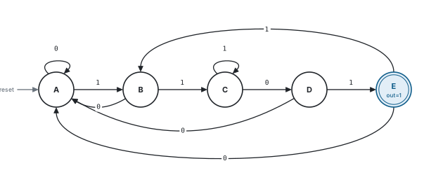
Method.
- Find the output: here it is state E.
- From reset, follow the chain of arcs that moves toward E. Their inputs spell the pattern: A →1 B →1 C →0 D →1 E, so the pattern is 1101.
- Check E’s outgoing arcs. E goes to B on a 1 and to A on a 0, exactly like A. So after a hit the machine starts over: non-overlapping. An overlapping 1101 detector would send E to C on a 1, because “11011” ends in “11”.
- Sanity-check one fallback: C loops on a 1, because “111” still ends in “11”. Correct.
“E behaves exactly like A, so the machine forgets the match. It’s a non-overlapping Moore detector for 1101.”
For RTL, apply the same steps to the case statement: find the state that drives detect, then trace its predecessors.
F6 Without an FSM: shift register + comparator
- Do it without an FSM.
- Use a shift register.
Tests: a second architecture, and the post-reset false match.
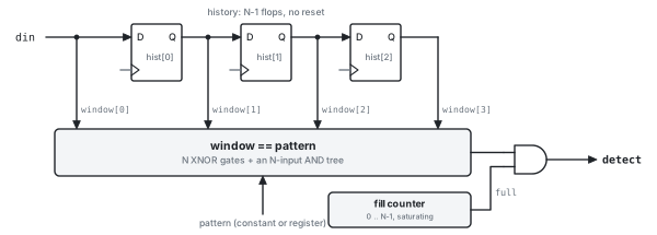
din, so the timing matches the Mealy FSM.// Detector for any N-bit pattern (N >= 2): a shift register plus a comparator.
// The pattern is a port, so it can be tied to a constant or driven by a
// config register. Timing matches seq_det_mealy: detect is high in the cycle
// the last bit of the pattern is on din.
module seq_det_shift #(
parameter int N = 4,
parameter bit OVERLAP = 1'b1
) (
input logic clk,
input logic rst_n, // asynchronous, active low
input logic [N-1:0] pattern, // pattern[N-1] is the first bit expected
input logic din,
output logic detect
);
localparam int CW = $clog2(N);
localparam logic [CW-1:0] LAST = CW'(N - 1);
logic [N-2:0] hist; // previous N-1 bits, hist[0] = newest
logic [N-1:0] window; // hist plus the bit arriving now
logic [CW-1:0] fill; // how many bits of hist are real data, saturates at N-1
logic full;
assign window = {hist, din};
assign full = (fill == LAST);
assign detect = full && (window == pattern);
// No reset needed: detect ignores hist until fill says it holds N-1 real bits
always_ff @(posedge clk) begin
hist <= window[N-2:0];
end
always_ff @(posedge clk or negedge rst_n) begin
if (!rst_n) fill <= '0;
else if (detect && !OVERLAP) fill <= '0; // next hit needs N new bits
else if (!full) fill <= fill + 1'b1;
end
endmoduleThe reset trap. An FSM gets “nothing matched yet” for free, because that is IDLE. A shift register doesn’t. Take the pattern 0011 with the history reset to 000: the stream 1, 1 makes the window read 0011 after only two bits. There are two cures:
- Fill counter (used in the listing). It counts real bits, saturating at N − 1, and masks
detectuntil the window is real. Clearing it on a hit gives non-overlap, and it meanshistneeds no reset at all. - Reset trick, for a fixed pattern only. Reset the history to copies of the complement of the pattern’s first bit:
000for 1011,111for 0011. Until real data fills the history, the oldest window bit can’t match, so no counter is needed.
PPA. N − 1 flops plus an N-bit comparator. For 1011 that is about 36 GE with the counter, or about 21 GE with the reset trick, against about 19 GE for the binary Mealy FSM (Section 5.1). Area grows linearly with N, but the logic is regular, and the pattern can change without a redesign.
Follow-up. Why does 1011 never fire falsely with a 000 reset? Its first bit is 1. A match needs the oldest window bit to be 1, and until three real bits have arrived the oldest bit is a reset 0.
F7 Programmable pattern, length and don’t-cares
- The pattern comes from a register.
- Support any pattern up to 32 bits, with don’t-care bits.
Tests: why an FSM stops being an option, and masked comparators.
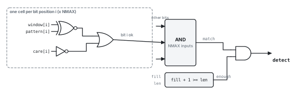
enough masks the window until len real bits have arrived.// Programmable detector: pattern, don't-care mask and length all come from
// registers. The newest bit is bit 0, so a len-bit pattern sits in
// pattern[len-1:0] with pattern[len-1] the first bit expected. Clear the
// care bits you don't want compared, and every care bit at or above len.
module seq_det_prog #(
parameter int NMAX = 32,
parameter bit OVERLAP = 1'b1
) (
input logic clk,
input logic rst_n, // asynchronous, active low
input logic [NMAX-1:0] pattern,
input logic [NMAX-1:0] care, // 1 = compare this bit
input logic [$clog2(NMAX+1)-1:0] len, // 1..NMAX, 0 disables
input logic din,
output logic detect
);
localparam int FW = $clog2(NMAX);
localparam int LW = $clog2(NMAX + 1);
localparam logic [FW-1:0] LAST = FW'(NMAX - 1);
logic [NMAX-2:0] hist; // previous NMAX-1 bits, hist[0] = newest
logic [NMAX-1:0] window;
logic [FW-1:0] fill; // real bits in hist, saturates at NMAX-1
logic [LW-1:0] have; // real bits in the window, including din
logic match, enough;
assign window = {hist, din};
assign match = &(~(window ^ pattern) | ~care);
assign have = LW'(fill) + 1'b1;
assign enough = (len != '0) && (have >= len);
assign detect = enough && match;
always_ff @(posedge clk) begin
hist <= window[NMAX-2:0]; // no reset: enough masks stale bits
end
always_ff @(posedge clk or negedge rst_n) begin
if (!rst_n) fill <= '0;
else if (detect && !OVERLAP) fill <= '0;
else if (fill != LAST) fill <= fill + 1'b1;
end
endmoduleSolution. An FSM’s next-state logic is the pattern, so a programmable pattern needs a programmable comparator. Each bit computes ok[i] = (window[i] ~^ pattern[i]) | ~care[i], and an NMAX-input AND combines them. A length register sets how many real bits are required before a hit (enough). Software keeps the care bits at and above len cleared.
Why not a programmable FSM? It can be done. Software computes the KMP transition table (2N entries of ⌈log₂N⌉ bits each) and the hardware looks it up. For N = 32 that is a 320-bit table plus a lookup mux, compared with about 100 flops for the comparator. And the table must be recomputed whenever the pattern changes.
PPA. The cost is 2 × NMAX register bits (pattern and care), NMAX − 1 history flops, NMAX XNOR and OR gates, and an AND tree about ⌈log₄NMAX⌉ gates deep.
Follow-up. What if software writes a new pattern mid-stream? Clear fill on the write so the next hit uses only new bits, or double-buffer the pattern and swap it at a frame boundary.
F8 A 64-bit sync word
- Detect a 64-bit sync word.
- It has to close timing at 2 GHz.
Tests: scaling, comparator depth, and pipelining.
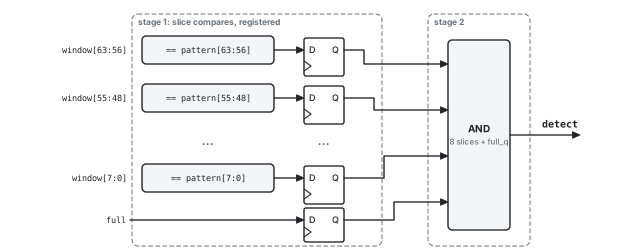
// Long pattern (e.g. a 64-bit sync word) with a two-stage compare. Stage 1
// registers one match bit per CHUNK-bit slice; stage 2 ANDs the N/CHUNK
// slice bits. detect is one cycle later than Mealy timing (Moore timing).
// Overlapping matches only.
module seq_det_pipe #(
  parameter int N     = 64,
  parameter int CHUNK = 8                   // N must be a multiple of CHUNK
) (
  input  logic         clk,
  input  logic         rst_n,               // asynchronous, active low
  input  logic [N-1:0] pattern,
  input  logic         din,
  output logic         detect
);

  localparam int K  = N / CHUNK;
  localparam int CW = $clog2(N);
  localparam logic [CW-1:0] LAST = CW'(N - 1);

  logic [N-2:0]  hist;
  logic [N-1:0]  window;
  logic [CW-1:0] fill;
  logic          full, full_q;
  logic [K-1:0]  part_q;                    // registered slice matches

  assign window = {hist, din};
  assign full   = (fill == LAST);

  always_ff @(posedge clk) begin            // datapath: no reset needed
    hist <= window[N-2:0];
    for (int k = 0; k < K; k++)
      part_q[k] <= (window[k*CHUNK +: CHUNK] == pattern[k*CHUNK +: CHUNK]);
  end

  always_ff @(posedge clk or negedge rst_n) begin
    if (!rst_n) begin
      fill   <= '0;
      full_q <= 1'b0;
    end else begin
      if (!full) fill <= fill + 1'b1;
      full_q <= full;
    end
  end

  assign detect = full_q && (&part_q);

endmodule
Solution. A 64-bit FSM has 65 states in 7 flops, but its next-state logic is irregular, must be redesigned for every sync word, and sits in a loop that cannot be pipelined. The shift register scales instead: 63 history flops and a 64-input compare. At high clock rates, split the compare into 8 slices of 8 bits, register each slice’s match, and AND the 8 registered bits in the next cycle. detect then arrives one cycle later, with Moore timing.
PPA. A 64-input AND takes about 4 to 6 gate stages, but split this way each pipeline stage needs only about 3 (the logical-effort numbers are in Section 5.2). The cost is 9 extra flops and one cycle of latency. Power is dominated by the 63 history flops toggling at the data rate, so clock-gate them when the link idles.
Follow-ups. Non-overlapping? Each hit is known one cycle late, so add a counter that masks detect for N − 1 cycles after every hit. What limits the clock rate now? The 8-input slice compare plus flop overhead. Use 4-bit slices to go faster.
F9 Two patterns: which one matched?
- Detect 1011 or 1101, and say which one matched.
Tests: sharing hardware, and the merged-automaton idea.
// K fixed N-bit patterns share one history register; each gets its own
// comparator. hit[k] is high in the cycle pattern k completes (Mealy timing),
// and several bits can be high at once if two patterns end together.
module seq_det_multi #(
  parameter int                  N    = 4,
  parameter int                  K    = 2,
  parameter logic [K-1:0][N-1:0] PATS = {4'b1101, 4'b1011}   // PATS[0] = 1011
) (
  input  logic         clk,
  input  logic         rst_n,       // asynchronous, active low
  input  logic         din,
  output logic [K-1:0] hit
);

  localparam int CW = $clog2(N);
  localparam logic [CW-1:0] LAST = CW'(N - 1);

  logic [N-2:0]  hist;
  logic [N-1:0]  window;
  logic [CW-1:0] fill;
  logic          full;

  assign window = {hist, din};
  assign full   = (fill == LAST);

  always_comb begin
    for (int k = 0; k < K; k++)
      hit[k] = full && (window == PATS[k]);
  end

  always_ff @(posedge clk) begin
    hist <= window[N-2:0];
  end

  always_ff @(posedge clk or negedge rst_n) begin
    if (!rst_n)     fill <= '0;
    else if (!full) fill <= fill + 1'b1;
  end

endmodule
Solution A: shared history. One history register feeds one comparator per pattern, and the result is a hit vector. Each extra pattern costs one comparator.
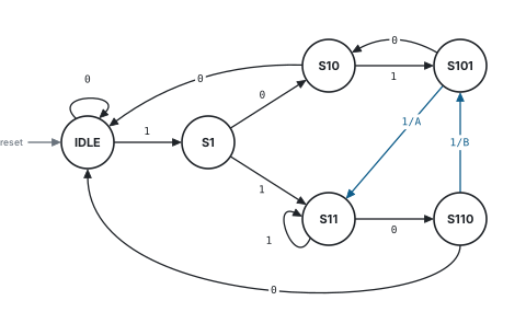
Solution B: one merged FSM. Apply the rule to both patterns at once. The states are the prefixes of either pattern: “”, 1, 10, 101, 11, 110. That is six states instead of four plus four, and cross-links appear. For example, a 1011 match lands in S11, which is halfway to 1101. On 101101 it reports A at bit 4 and B at bit 6. This is the Aho–Corasick automaton.
PPA. The merged FSM uses the fewest flops (three), but deriving it by hand gets hard quickly, and any change of pattern means a redesign. The shared history needs N − 1 flops plus K comparators, and extending it is trivial.
Follow-up. What if both patterns end in the same cycle (for example 1011 and 011)? Both hit bits are set. Add a priority encoder if a single ID is needed.
F10 Don’t-cares and error tolerance
- Some pattern bits are don’t-care, as in 1x01.
- Tolerate up to k bit errors in the sync word.
Tests: masking, and the cost of counting.
Don’t-cares. Use the care mask of F7: a bit with care[i] = 0 always passes. For a fixed pattern, synthesis simply removes those comparator inputs.
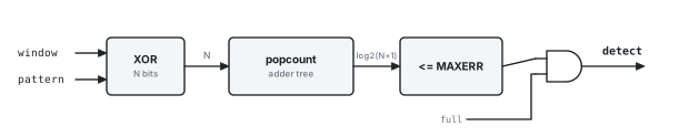
Error tolerance. Count the mismatches and accept up to k of them: popcount(window ^ pattern) <= MAXERR.
// Error-tolerant match: fires when the last N bits differ from the pattern
// in at most MAXERR positions (a sync word on a noisy link). The mismatch
// count is the popcount of window XOR pattern.
module seq_det_tol #(
  parameter int N      = 16,
  parameter int MAXERR = 2
) (
  input  logic         clk,
  input  logic         rst_n,       // asynchronous, active low
  input  logic [N-1:0] pattern,
  input  logic         din,
  output logic         detect
);

  localparam int CW = $clog2(N);
  localparam int EW = $clog2(N + 1);
  localparam logic [CW-1:0] LAST  = CW'(N - 1);
  localparam logic [EW-1:0] LIMIT = EW'(MAXERR);

  logic [N-2:0]  hist;
  logic [N-1:0]  window, diff;
  logic [CW-1:0] fill;
  logic [EW-1:0] errs;              // number of mismatching bits
  logic          full;

  assign window = {hist, din};
  assign diff   = window ^ pattern;
  assign full   = (fill == LAST);

  always_comb begin
    errs = '0;
    for (int i = 0; i < N; i++)
      errs = errs + EW'(diff[i]);
  end

  assign detect = full && (errs <= LIMIT);

  always_ff @(posedge clk) begin
    hist <= window[N-2:0];
  end

  always_ff @(posedge clk or negedge rst_n) begin
    if (!rst_n)     fill <= '0;
    else if (!full) fill <= fill + 1'b1;
  end

endmodule
PPA. Popcount is an adder tree. It needs about N − ⌈log₂(N+1)⌉ full adders, because each full adder removes one bit: about 11 for N = 16 and 57 for N = 64. Each one is roughly 28 transistors as a static-CMOS mirror adder. That dwarfs the XOR row, so pipeline the tree with registers between adder levels. Real links use this for frame alignment on noisy channels.
Follow-up. Is there anything cheaper for k = 1? Yes: $onehot0(window ^ pattern), which means “zero or one bits differ”. It costs about 2N gates, with no adders.
F11 An input valid, with bubbles
- Bits come with a valid signal, and there are idle cycles.
- The stream can stall.
Tests: enables, output qualification, and clock gating.
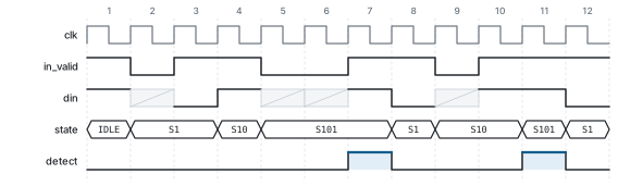
in_valid low) freeze the state. The hits in cycles 7 and 11 complete on the 4th and 7th valid bits; the second one overlaps the first.// Mealy detector for 1011 on a stream with bubbles: a bit counts only when
// in_valid is high. The state holds on idle cycles and detect is qualified
// by in_valid, so a bubble can neither complete nor break a match.
module seq_det_valid #(
parameter bit OVERLAP = 1'b1
) (
input logic clk,
input logic rst_n, // asynchronous, active low
input logic in_valid,
input logic din,
output logic detect
);
typedef enum logic [1:0] {
IDLE = 2'd0,
S1 = 2'd1,
S10 = 2'd2,
S101 = 2'd3
} state_t;
state_t state, state_nxt;
always_ff @(posedge clk or negedge rst_n) begin
if (!rst_n) state <= IDLE;
else if (in_valid) state <= state_nxt; // an enable: synthesis can clock-gate here
end
always_comb begin
case (state)
IDLE : state_nxt = din ? S1 : IDLE;
S1 : state_nxt = din ? S1 : S10;
S10 : state_nxt = din ? S101 : IDLE;
S101 : state_nxt = din ? (OVERLAP ? S1 : IDLE) : S10;
default: state_nxt = IDLE;
endcase
end
assign detect = in_valid && din && (state == S101);
endmoduleSolution. Advance the state only when in_valid is high, and qualify detect with in_valid. A bubble then can neither complete nor break a match.
Forgetting to qualify detect with in_valid. In S101, a bubble on which din happens to be 1 would fire on a bit that doesn’t exist.
PPA. The if (in_valid) enable is a clock-gating opportunity. Synthesis replaces the enable mux with an integrated clock-gating cell (Section 5.3), so the state flops are not clocked on idle cycles. For the shift-register version, gate the whole history register the same way: that is where most of its power goes.
Follow-up. What about valid and ready? The detector never applies back-pressure, so it just watches the handshake: a bit counts when valid && ready.
F12 W bits per clock
- Four bits arrive every clock.
- The SerDes delivers 32 bits per cycle.
Tests: matches that straddle words, and area-for-throughput.
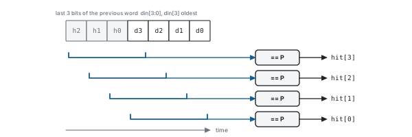
// N-bit pattern on a stream that arrives W bits per clock. din[W-1] is the
// oldest bit of each word. hit[j] = a match ends at din[j], so one word can
// report several (overlapping) matches, including ones that straddle words.
module seq_det_par #(
  parameter int N = 4,
  parameter int W = 4
) (
  input  logic         clk,
  input  logic         rst_n,       // asynchronous, active low
  input  logic [N-1:0] pattern,
  input  logic [W-1:0] din,
  output logic [W-1:0] hit
);

  localparam int FW = $clog2(N);
  localparam logic [FW-1:0] LAST = FW'(N - 1);

  logic [N-2:0]   hist;             // last N-1 bits before this word, [0] newest
  logic [N+W-2:0] ext;              // hist followed by the current word
  logic [FW-1:0]  fill;             // real bits in hist, saturates at N-1
  int             sum;              // fill + W without overflow

  assign ext = {hist, din};
  assign sum = int'(fill) + W;

  // a match ending at din[j] needs j+N-W real history bits
  always_comb begin
    for (int j = 0; j < W; j++)
      hit[j] = (ext[j +: N] == pattern) && (int'(fill) >= j + N - W);
  end

  always_ff @(posedge clk) begin
    hist <= ext[N-2:0];
  end

  always_ff @(posedge clk or negedge rst_n) begin
    if (!rst_n)             fill <= '0;
    else if (sum >= N - 1)  fill <= LAST;
    else                    fill <= sum[FW-1:0];
  end

endmodule
Solution. Keep the last N − 1 bits as history. Together with the new word they form an extended window of N + W − 1 bits. Compare at all W offsets: hit[j] means a match ends at din[j], including matches that straddle two words.
Why not an FSM? It would have to take W steps per clock, which means W copies of the next-state logic chained inside the feedback loop. That makes the loop W times longer, and it still can’t be pipelined.
Non-overlapping. Several hits in one word can overlap. Keep the oldest, and mask any later hit that starts before the previous one ended. That takes a priority chain across the offsets, plus a mask carried into the next word.
PPA. Area is about W × N XNOR and AND gates. The critical path is unchanged: one N-input compare. The same throughput at 1/W the clock rate also allows a lower supply voltage (Section 5.3).
Follow-up. How would you report a single match position? Priority-encode hit.
F13 Count the matches, interrupt on the k-th
- Count the matches.
- Raise an interrupt on the third match.
Tests: composing blocks, and corner cases.

// Counts 1011 matches and raises a sticky interrupt on the IRQ_AT-th match.
// clr (write-1-to-clear) zeroes the count and the interrupt; a match in the
// same cycle as clr is counted as the first match of the new run.
module seq_det_count #(
  parameter int CW     = 8,
  parameter int IRQ_AT = 3          // 1 <= IRQ_AT < 2**CW
) (
  input  logic          clk,
  input  logic          rst_n,      // asynchronous, active low
  input  logic          din,
  input  logic          clr,
  output logic [CW-1:0] count,      // saturates at all ones
  output logic          irq
);

  localparam logic [CW-1:0] TRIP = CW'(IRQ_AT - 1);   // count just before the IRQ_AT-th hit

  logic          hit;
  logic [CW-1:0] base;              // count after an optional clear

  seq_det_mealy #(.OVERLAP(1'b1)) u_det (
    .clk(clk), .rst_n(rst_n), .din(din), .detect(hit));

  assign base = clr ? '0 : count;

  always_ff @(posedge clk or negedge rst_n) begin
    if (!rst_n) begin
      count <= '0;
      irq   <= 1'b0;
    end else begin
      if (hit && (base != '1)) count <= base + 1'b1;
      else                     count <= base;
      irq <= (irq && !clr) || (hit && (base == TRIP));
    end
  end

endmodule
Corner cases to raise yourself.
- Saturation: the count must not wrap back to 0.
- A hit in the same cycle as
clr: here the clear wins, but the hit still counts as the first of the new run.
PPA. CW flops, an incrementer (a CW-bit half-adder chain) and a compare, so it is small. The interrupt comes straight off a flop, so it can safely leave the block.
F14 A glitch-free output
- detect must be glitch-free.
- detect drives logic in another clock domain.
Tests: knowing where glitches come from, and three standard cures.
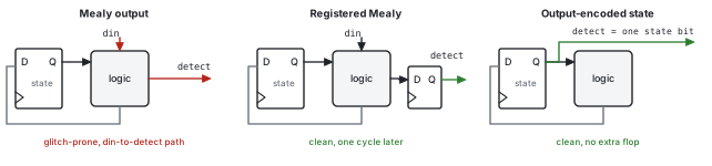
detect. Only the first is a combinational function of din.Why it glitches. A Mealy output, or a binary decode of the state, is a combinational function of signals that settle at different times. Suppose state moves from S1 (01) to S10 (10) while a new din = 1 arrives. For a moment the bits can read 11, which is S101, together with din = 1, and detect pulses (Figure 5.4).
Three cures.
- Register the Mealy output (Listing 1.3).
- Output-encode the state so that
detectis a flop. In the binary Moore machineS1011= 100, so with the unused codes treated as don’t-cares,detect = state[2]. - Go one-hot, so that
detectis simply theS1011flop.
// Moore detector for 1011 with one-hot state. Each flop's next value is the
// OR of its incoming arcs, and detect is a flop output: no decode, no glitch.
// Any illegal code (no bit or several bits set) returns to IDLE.
module seq_det_onehot #(
  parameter bit OVERLAP = 1'b1
) (
  input  logic clk,
  input  logic rst_n,             // asynchronous, active low
  input  logic din,
  output logic detect
);

  localparam int IDLE = 0, S1 = 1, S10 = 2, S101 = 3, S1011 = 4;   // bit positions

  logic [4:0] st, st_nxt;
  logic       legal;

  // exactly one bit set: non-zero, and clearing the lowest set bit leaves zero
  assign legal = (st != '0) && ((st & (st - 5'd1)) == '0);

  always_comb begin
    st_nxt[IDLE]  = ~din & (st[IDLE] | st[S10]  | (~OVERLAP & st[S1011]));
    st_nxt[S1]    =  din & (st[IDLE] | st[S1]   | st[S1011]);
    st_nxt[S10]   = ~din & (st[S1]   | st[S101] | ( OVERLAP & st[S1011]));
    st_nxt[S101]  =  din &  st[S10];
    st_nxt[S1011] =  din &  st[S101];
  end

  always_ff @(posedge clk or negedge rst_n) begin
    if (!rst_n)      st <= 5'b00001;
    else if (!legal) st <= 5'b00001;
    else             st <= st_nxt;
  end

  assign detect = st[S1011];

endmodule
PPA. The registered Mealy costs one flop and one cycle. The output-encoded state is free, provided you choose the encoding. One-hot costs N + 1 flops but gives the shallowest next-state logic. It also needs recovery from illegal states: without the legal check, all-zeros would lock the machine up forever.
A glitch only matters when detect drives something asynchronous: another clock domain, an asynchronous set or reset, or a pin. Inside one clock domain, static timing analysis guarantees detect settles before the capturing edge. There the glitch only costs dynamic power, one charge and discharge of every node it reaches.
F15 N consecutive 1s
- Detect 8 consecutive 1s.
- Flag when din has been high for N cycles.
Tests: recognizing when an FSM is really a counter.
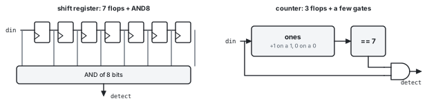
// Detects N consecutive 1s with a saturating counter instead of an N-bit
// shift register: $clog2(N) flops instead of N-1. Mealy timing; with
// OVERLAP = 1 it keeps firing while the run continues.
module run_det #(
  parameter int N       = 8,        // N >= 2
  parameter bit OVERLAP = 1'b1
) (
  input  logic clk,
  input  logic rst_n,               // asynchronous, active low
  input  logic din,
  output logic detect
);

  localparam int CW = $clog2(N);
  localparam logic [CW-1:0] LAST = CW'(N - 1);

  logic [CW-1:0] ones;              // 1s just before this bit, saturates at N-1

  assign detect = din && (ones == LAST);

  always_ff @(posedge clk or negedge rst_n) begin
    if (!rst_n)                  ones <= '0;
    else if (!din)               ones <= '0;
    else if (detect && !OVERLAP) ones <= '0;
    else if (ones != LAST)       ones <= ones + 1'b1;
  end

endmodule
Solution. The prefix rule gives a chain of N states whose only meaning is “how many 1s so far”. That is a counter. Count the 1s (saturating), and clear the count on a 0.
PPA. ⌈log₂N⌉ flops instead of N − 1 flops plus an N-input AND. For N = 8 that is 3 flops versus 7. For a timeout of N = 1000 it is 10 versus 999.
Variants. “Exactly N ones, then a 0”: fire on a 0 when the count equals N. “At least N”: the overlapping version above.
F16 Divisible by 3 (and by K)
- A binary number arrives MSB first. Flag when the number so far is divisible by 3.
- Now do it for 5.
Tests: choosing the right thing to remember.
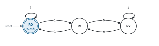
Solution. Remember the remainder so far. Appending bit b turns the value v into 2v + b, so the remainder goes from r to (2r + b) mod 3. That needs three states in two flops.
| Remainder r | Next on 0 | Next on 1 |
|---|---|---|
| 0 | 0 | 1 |
| 1 | 2 | 0 |
| 2 | 1 | 2 |
// A binary number arrives MSB first, one bit per clock. is_mult is high
// while the number received so far is a multiple of K (after reset the
// number is empty, i.e. 0). Appending bit b maps remainder r to
// (2r + b) mod K, and since 2r + b < 2K one compare-and-subtract replaces
// a divider.
module div_k_det #(
  parameter int K = 3               // K >= 2
) (
  input  logic clk,
  input  logic rst_n,               // asynchronous, active low
  input  logic din,
  output logic is_mult              // Moore: covers every bit up to the last edge
);

  localparam int RW = $clog2(K);
  localparam logic [RW:0] KV = (RW + 1)'(K);

  logic [RW-1:0] rem;
  logic [RW:0]   twice;             // 2*rem + din, one bit wider

  assign twice = {rem, din};

  always_ff @(posedge clk or negedge rst_n) begin
    if (!rst_n)           rem <= '0;
    else if (twice >= KV) rem <= RW'(twice - KV);
    else                  rem <= RW'(twice);
  end

  assign is_mult = (rem == '0);

endmodule
Generalization. For any K, since r < K, the value 2r + b is always less than 2K. One compare-and-subtract replaces a divider, and the design needs ⌈log₂K⌉ flops however long the number gets.
LSB-first variant. Each new bit is worth 2^k, and 2^k mod 3 alternates 1, 2, 1, 2… So the state must also track the parity of the bit position: 6 states.
Follow-up. Divisible by 4? The number is a multiple of 4 exactly when its last two bits are 00, which is a sequence detector for 00.
F17 A multi-byte header in a byte stream
- Find the 3-byte header A5 5A C3 in a byte stream.
- Bytes come with a valid.
Tests: applying the rule to symbols instead of bits.
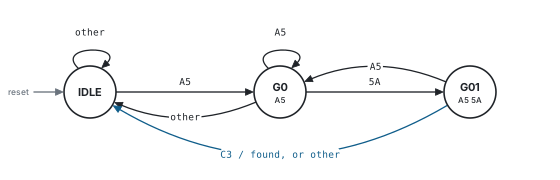
// Finds the 3-byte header H0 H1 H2 in a byte stream. Same rule as the bit
// detectors, applied to bytes: the state is the longest header prefix the
// received bytes end with. Terms that compare parameters (e.g. H1 == H0)
// are constants, so synthesis folds them away for a given header.
module hdr_det #(
  parameter logic [7:0] H0 = 8'hA5,
  parameter logic [7:0] H1 = 8'h5A,
  parameter logic [7:0] H2 = 8'hC3
) (
  input  logic       clk,
  input  logic       rst_n,         // asynchronous, active low
  input  logic       in_valid,
  input  logic [7:0] din,
  output logic       found          // high with the byte that completes the header
);

  typedef enum logic [1:0] {
    IDLE = 2'd0,                    // matched nothing
    G0   = 2'd1,                    // matched H0
    G01  = 2'd2                     // matched H0 H1
  } state_t;

  state_t state, state_nxt;
  logic   is0, is1, is2;

  assign is0 = (din == H0);
  assign is1 = (din == H1);
  assign is2 = (din == H2);

  always_comb begin
    state_nxt = IDLE;
    case (state)
      IDLE: if (is0) state_nxt = G0;
      G0  : if      (is1) state_nxt = G01;
            else if (is0) state_nxt = G0;
      G01 : if (is2) begin                     // match: keep the longest border
              if      (H1 == H0 && H2 == H1) state_nxt = G01;
              else if (H2 == H0)             state_nxt = G0;
            end
            else if (H1 == H0 && is1)        state_nxt = G01;
            else if (is0)                    state_nxt = G0;
      default: state_nxt = IDLE;
    endcase
  end

  always_ff @(posedge clk or negedge rst_n) begin
    if (!rst_n)        state <= IDLE;
    else if (in_valid) state <= state_nxt;
  end

  assign found = in_valid && (state == G01) && is2;

endmodule
Solution. Compare din against each header byte, which takes three 8-bit comparators. The FSM remembers how many header bytes have matched. If the header repeats a byte, the fallback arcs change. The listing handles every possible header by writing the fallback conditions in terms of the parameters (for example H1 == H0), which synthesis folds to constants.
PPA. The FSM needs 2 flops and three 8-bit comparators (about 24 XNOR gates and 3 AND8 gates). A byte-wide shift register would need 16 flops and a 24-bit comparator. The FSM wins on flops; the shift register wins once the header is programmable.
Follow-up. What about the header A5 A5 5A? After “A5 A5”, a third A5 keeps the machine in G01, and the H1 == H0 terms handle exactly that case.
F18 Two 1s within T cycles
- Fire when a 1 arrives within T cycles of the previous 1.
- Detect two requests that are closer than T cycles.
Tests: patterns defined by time rather than by bits.
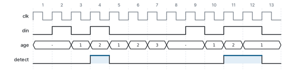
// Fires when a 1 arrives no more than T cycles after the previous 1
// (T = 1 means back-to-back 1s). A saturating age counter replaces a
// T-bit shift register plus a T-input OR.
module win_det #(
  parameter int T = 4               // T >= 1
) (
  input  logic clk,
  input  logic rst_n,               // asynchronous, active low
  input  logic din,
  output logic detect
);

  localparam int AW = $clog2(T + 2);
  localparam logic [AW-1:0] NONE  = AW'(T + 1);   // no 1 inside the window
  localparam logic [AW-1:0] LIMIT = AW'(T);

  logic [AW-1:0] age;               // cycles since the last 1

  assign detect = din && (age <= LIMIT);

  always_ff @(posedge clk or negedge rst_n) begin
    if (!rst_n)           age <= NONE;
    else if (din)         age <= AW'(1);
    else if (age != NONE) age <= age + 1'b1;
  end

endmodule
Solution. The state to remember is “cycles since the last 1”, which is a saturating age counter. Fire when a 1 arrives with an age of T or less.
PPA. ⌈log₂(T+2)⌉ flops, instead of a T-bit shift register plus a T-input OR.
Variants. “A 1 followed by a 0 within T cycles”, or “no 1 for T cycles” (a watchdog timeout), use the same counter.
F19 A debouncer
- Design a debouncer for a push button.
- The output may change only after the input has been stable for N cycles.
Tests: synchronizing an asynchronous input, then detecting a run.
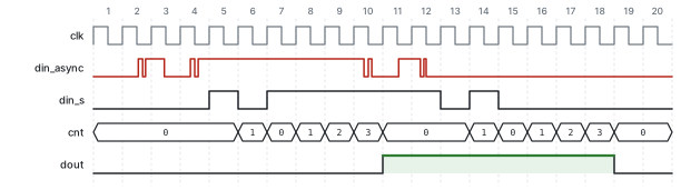
dout follows only after 4 equal samples.// Debouncer for a noisy asynchronous input such as a push button. The input
// is synchronized first; dout then changes only after the synchronized
// input has held its new value for N consecutive clocks.
module debounce #(
parameter int N = 16 // N >= 2
) (
input logic clk,
input logic rst_n, // asynchronous, active low
input logic din_async,
output logic dout
);
localparam int CW = $clog2(N);
localparam logic [CW-1:0] LAST = CW'(N - 1);
logic [1:0] sync; // 2-flop synchronizer
logic din_s;
logic [CW-1:0] cnt; // cycles din_s has differed from dout
always_ff @(posedge clk or negedge rst_n) begin
if (!rst_n) sync <= '0;
else sync <= {sync[0], din_async};
end
assign din_s = sync[1];
always_ff @(posedge clk or negedge rst_n) begin
if (!rst_n) begin
cnt <= '0;
dout <= 1'b0;
end else if (din_s == dout) begin
cnt <= '0;
end else if (cnt == LAST) begin
cnt <= '0;
dout <= din_s;
end else begin
cnt <= cnt + 1'b1;
end
end
endmoduleSolution. There are two parts. First, a two-flop synchronizer, because the button is asynchronous (Section 5.5). Second, a run detector (F15) on the condition “the synchronized input differs from the output”: after N consecutive samples, the output follows.
Sizing. Switch bounce lasts milliseconds. 10 ms at 100 MHz is 1,000,000 cycles, which needs a 20-bit counter. It is better to sample on a slow tick, say a 1 kHz enable. Then N = 10 needs only a 4-bit counter, and the counter runs only on ticks, which saves power.
Feeding the raw button signal straight into the counter logic without synchronizing it first. The flops that sample it can go metastable.
F20 How would you verify it?
- How would you verify your detector?
- Write an assertion for it.
Tests: verification thinking: a spec-based model, stimulus quality, and coverage.
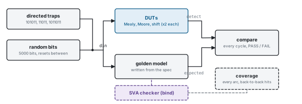
The testbench in this repository (tb_seq_det.sv) has four parts:
- A golden model written from the spec (“the last 4 bits are 1011”), never from the RTL.
- Directed trap streams whose expected hit counts were worked out by hand. They check the model as well as the design.
- 5,000 random bits, with resets between segments.
- A check of every DUT output on every cycle, comparing Moore outputs with the model’s previous cycle, plus one final check after the last bit.
  // Drive one bit and check every DUT before the rising edge that consumes it.
  task automatic drive_bit(input logic b);
    din = b;
    #1;
    win     = {win[2:0], b};
    seen_ov = seen_ov + 1;
    seen_no = seen_no + 1;
    exp_ov  = (seen_ov >= 4) && (win == PAT);
    exp_no  = (seen_no >= 4) && (win == PAT);
    if (exp_no) seen_no = 0;

    check("mealy_ov", mealy_ov, exp_ov);
    check("mealy_no", mealy_no, exp_no);
    check("shift_ov", shift_ov, exp_ov);
    check("shift_no", shift_no, exp_no);
    check("moore_ov", moore_ov, exp_ov_q);
    check("moore_no", moore_no, exp_no_q);

    if (exp_ov) hits_ov++;
    if (exp_no) hits_no++;
    exp_ov_q = exp_ov;
    exp_no_q = exp_no;
    @(negedge clk);
endtaskAssertions. A checker bound to the design keeps its own record of the last bits and asserts detect == want on every cycle. Its cover properties prove that the stimulus exercised the tricky arcs.
// Assertion checker for any 1011 detector with Mealy timing. It keeps its
// own record of the last three bits and checks detect against the spec
// every cycle. Attach it without editing the design:
//   bind seq_det_mealy seq_det_checker #(.OVERLAP(OVERLAP)) u_chk (.*);
module seq_det_checker #(
  parameter bit OVERLAP = 1'b1
) (
  input logic clk,
  input logic rst_n,
  input logic din,
  input logic detect
);

  logic [2:0] prev;                 // previous three bits, prev[0] = newest
  int         seen;                 // how many of them may be part of a match
  logic       want;                 // what detect must be this cycle

  assign want = (seen >= 3) && ({prev, din} == 4'b1011);

  always_ff @(posedge clk or negedge rst_n) begin
    if (!rst_n) begin
      prev <= '0;
      seen <= 0;
    end else begin
      prev <= {prev[1:0], din};
      if (want && !OVERLAP) seen <= 0;
      else if (seen < 3)    seen <= seen + 1;
    end
  end

  a_spec: assert property (@(posedge clk) disable iff (!rst_n) detect == want)
    else $error("detect=%b but the last 4 bits are %b", detect, {prev, din});

  // the stimulus must exercise the tricky arcs at least once
  c_fallback_s101: cover property (@(posedge clk) disable iff (!rst_n)
                     din ##1 !din ##1 din ##1 !din ##1 din ##1 din);   // 101011
  c_selfloop_s1:   cover property (@(posedge clk) disable iff (!rst_n)
                     din ##1 din ##1 !din ##1 din ##1 din);            // 11011
  c_back_to_back:  cover property (@(posedge clk) disable iff (!rst_n)
                     detect ##3 detect);                               // 1011011

endmodule
Coverage to ask for:
- every state and every arc (8 for the Mealy machine)
- back-to-back hits
- a hit immediately after reset
- a reset in the middle of a match
F21 Where is the critical path?
- Where is the critical path?
- How would you make this run faster?
Tests: timing thinking at the RTL level.
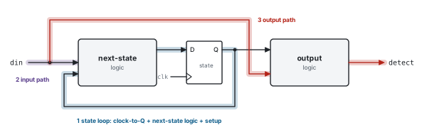
- The state loop: Tclk ≥ tclk-to-Q + tnext-state + tsetup, plus a margin for skew and jitter. It cannot be pipelined: putting a register in the loop changes the machine.
- The input path: an upstream flop, the wire,
din, the next-state logic, then setup. It is budgeted with the block’s input delay. - The Mealy output path:
din, the output logic,detect, then the next block. It spans two blocks’ timing budgets, so register it.
Speed-ups, cheapest first:
- Register the outputs.
- Switch to one-hot encoding: two-level next-state logic, and
detectcomes straight off a flop. - Register
din(this costs a cycle). - For a shift-register design, pipeline the compare (F8).
- For W bits per clock, use comparators rather than a chained FSM (F12).
The loop is only a few gate stages, so its delay depends on gate choice and fan-out rather than on logic depth. Prefer NAND to NOR, and keep the fan-out of din low. For example, one-hot fans din out to every state flop, so buffer it. Section 5.2 puts numbers on this.
F22 Convert Mealy to Moore, and back
- Convert your Mealy machine to a Moore machine.
- And back again.
Tests: understanding both models, not just memorizing them.
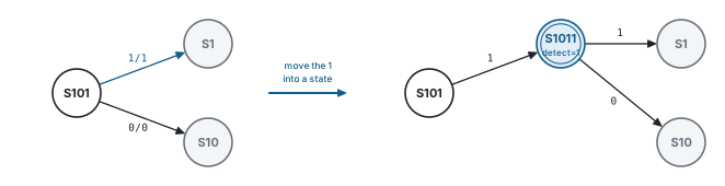
Mealy to Moore. Move the outputs from the arcs into the states. Split every state whose incoming arcs carry different output values into one copy per value. For 1011, only the arc S101 --1/1--> S1 outputs a 1. So S1 splits into S1 (output 0) and a new state S1011 (output 1), and both keep S1’s outgoing arcs. At most one new state is needed per distinct output on a state’s incoming arcs.
Moore to Mealy. Put each state’s output on its incoming arcs, so each arc outputs its destination state’s value. Then merge any states that have become equivalent: here S1011 merges back into S1. The output moves one cycle earlier.
“The conversion doesn’t change what gets detected, only when detect appears, and how many states it takes.”
F23 din arrives from another clock domain
- din comes from another clock domain.
- The serial link runs on its own clock.
Tests: knowing what a synchronizer can and cannot do.
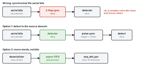
The wrong answer. A two-flop synchronizer is for one slow control signal. A serial stream carries a new bit on every source clock, so the destination clock samples some bits twice and misses others. Those bits cannot be recovered.
The right answers.
- Run the detector in the source domain; a source-synchronous clock usually arrives with the data. Then send only the rare
detectpulse across, using a toggle synchronizer. - Deserialize in the source domain, pass W-bit words through an asynchronous FIFO with Gray-coded pointers, and detect with
seq_det_par(F12) on the other side. - Oversample and recover the clock (clock and data recovery). That is a PHY problem, not an RTL one.
Section 5.5 explains why synchronizers work, and how reliable they are.
F24 A sequence generator
- Generate the sequence 1011 repeatedly.
- Design a sequence generator.
Tests: the dual of detection, and the flop-versus-logic trade-off.
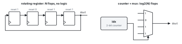
// Generates PATTERN repeatedly, MSB first (1011 1011 ...). USE_CNT picks the
// structure: a rotating register (N flops, no logic) or a counter that
// indexes the constant ($clog2(N) flops plus a small mux).
module seq_gen #(
  parameter int           N       = 4,        // N >= 2
  parameter logic [N-1:0] PATTERN = 4'b1011,
  parameter bit           USE_CNT = 1'b1
) (
  input  logic clk,
  input  logic rst_n,               // asynchronous, active low
  output logic dout
);

  if (USE_CNT) begin : g_cnt
    localparam int CW = $clog2(N);
    localparam logic [CW-1:0] LAST = CW'(N - 1);

    logic [CW-1:0] idx;             // position of dout within the pattern

    always_ff @(posedge clk or negedge rst_n) begin
      if (!rst_n)           idx <= '0;
      else if (idx == LAST) idx <= '0;
      else                  idx <= idx + 1'b1;
    end

    assign dout = PATTERN[LAST - idx];
  end else begin : g_rot
    logic [N-1:0] rot;

    always_ff @(posedge clk or negedge rst_n) begin
      if (!rst_n) rot <= PATTERN;
      else        rot <= {rot[N-2:0], rot[N-1]};
    end

    assign dout = rot[N-1];
  end

endmodule
Solution. There are two options. Rotate a register that resets to the pattern (N flops, no logic). Or index the constant with a counter ($clog2(N) flops plus an N:1 mux). A generator and a detector together form a built-in self-test pair. Replacing the pattern with an LFSR turns them into a PRBS generator and checker.
PPA. The rotating register is the fastest (flop to flop), but uses the most flops. The counter uses the fewest flops, and its mux of constants reduces to a few gates.
Chapter 4RTL coding practices
Interviewers read your RTL for correctness first and discipline second. The rules below are the ones production reviewers check. Every example is compile-checked, and each “bad” version is legal SystemVerilog that does something other than what its author meant.
4.1 The FSM template
Listing 1.1 is the template for every FSM in this book. It follows eight rules.
- Three pieces. One
always_fffor the state register, using non-blocking<=. Onealways_combfor the next state, using blocking=. The output is anassign(Mealy) or a decode of the state (Moore). - Enums with explicit encodings, such as
typedef enum logic [1:0] {IDLE = 2'd0, ...}, and named after the matched prefix. Waveforms then show state names, and the width is stated. - A
defaultin everycase. No path can leave the next state unassigned (so no latch), and illegal codes recover. - Parameters for behaviour, and typed localparams for constants. For example,
OVERLAPis a parameter, andlocalparam logic [CW-1:0] LAST = CW'(N - 1)makes comparisons type-match, so lint stays quiet. - Reset only what needs it. Control state gets a reset. Datapath flops that are masked anyway, such as the shift-register history, go in their own
always_ffwith no reset. - Register every output that leaves the block.
- Comments state constraints and intent (“no reset:
fillmasks stale bits”), never what the next line does. - One module per file, and
`timescalein every file or in none. The LRM makes mixing the two an error, slang flags it, and simulators disagree about it.
Figure 1.4 shows the structure these rules produce: next-state logic, the state register, and the output logic.
4.2 Bad versus good
A latch from an incomplete assignment
always_comb begin
  if (load) nxt = d;          // no else: nxt must hold its value -> latch
endalways_comb begin
nxt = cur; // default first: every path assigns nxt
if (load) nxt = d;
endIf any path through an always_comb leaves a variable unassigned, the variable has to remember its old value, and that means a latch. Assigning defaults at the top of the block rules this out for every path.
Blocking assignments in a flop block
always_ff @(posedge clk) begin
  b = a;                      // blocking: c sees the NEW b at this edge,
  c = b;                      // so the two-stage pipe collapses to one
endalways_ff @(posedge clk) begin
b <= a;
c <= b; // c gets the OLD b: a real two-stage pipe
endWith blocking assignments, c reads the value of b that was just written, so the pipeline loses a stage. Simulation may also race against other blocks that read b. Use <= in always_ff and = in always_comb, always.
Reset and no-reset flops in one block
always_ff @(posedge clk or negedge rst_n) begin
  if (!rst_n) fill <= '0;
  else begin
    fill <= fill + 1'b1;
    hist <= {hist[1:0], din}; // no reset value: rst_n turns into hist's enable
  end
endalways_ff @(posedge clk or negedge rst_n) begin
if (!rst_n) fill <= '0;
else fill <= fill + 1'b1;
end
always_ff @(posedge clk) begin // datapath flops: no reset, no enable
hist <= {hist[1:0], din};
endhist is not assigned in the reset branch, so while rst_n is low it must hold its value. Synthesis builds that with a hold mux or an enable, which costs area and puts rst_n in the data path. Flops without a reset belong in their own block.
What unique case promises
always_comb begin
  unique case (sel)           // promises: items exclusive AND complete
    2'd0: y = a;
    2'd1: y = b;
    2'd2: y = c;
  endcase                     // sel == 3: simulation warns and holds y,
end // synthesis may treat it as don't-carealways_comb begin
case (sel)
2'd0: y = a;
2'd1: y = b;
2'd2: y = c;
default: y = 1'b0; // complete by construction
endcase
endunique tells every tool that the case items are mutually exclusive and that one of them always matches. Synthesis may use that promise to simplify the logic. If the promise is broken (sel == 3 here), simulation warns and holds y, while the netlist does something else. Use unique only when the items really are complete, and prefer a plain case with default.
Incomplete sensitivity lists
always @(a or b)              // c is missing: simulation holds y when only c
y = a & b & c; // changes, but synthesis builds a plain AND3always_comb y = a & b & c; // sensitivity is inferred; latches are flaggedThe old Verilog style simulates as a latch on c but synthesizes to a plain AND gate: a mismatch between simulation and synthesis. always_comb infers the sensitivity for you, runs once at time 0, and lets tools flag latches and multiple drivers.
Widths from $clog2
logic [$clog2(N)-1:0] cnt;    // N = 8: 3 bits hold 0..7 ...
assign done = (cnt == N); // ... so cnt == 8 can never be truelocalparam int CW = $clog2(N + 1); // N = 8: 4 bits hold 0..8
localparam logic [CW-1:0] LAST = CW'(N); // typed constant: no sign-compare warning
logic [CW-1:0] cnt;
assign done = (cnt == LAST);$clog2(N) bits hold the values 0 to N − 1. A counter that must reach N needs $clog2(N + 1) bits. Compare against a typed constant; comparing a logic vector with an int draws sign warnings.
Default branches: don’t-care or recovery?
default: nxt_a = state_t'('x); // don't care: smallest logic, no recoverydefault: nxt_b = IDLE; // any illegal code returns to IDLEAn 'x default lets synthesis treat unused codes as don’t-cares, which is how the Moore machine gets detect = state[2] for free (F14). It also turns unexpected states into visible X’s in simulation. A recovery default costs a little logic, but it brings the machine back after a supply glitch or an upset. Either way, synthesis may prove that unused states are unreachable and delete the recovery logic. If recovery must survive, enable your tool’s safe-FSM option.
Enums are strongly typed
These lines do not compile, by design:
state_nxt = 2'd3;            // error: an integer is not a state_t
state_nxt = state + 1;       // error: enum arithmetic yields int
state_nxt = state_t'(2'd3);  // compiles, but bypasses the names: avoid
Telling synthesis which encoding to use
(* fsm_encoding = "one_hot" *) state_t state; // Vivado; other tools use their own directiveTools re-encode FSMs by default: FPGA tools usually pick one-hot, and ASIC tools pick whatever meets timing. If the encoding matters, constrain it. That applies when you rely on an output-encoded state (F14), a Gray code for power (Section 5.3), or a specific code that software reads back.
4.3 Testbench practices
- Write the golden model from the spec, never by copying the RTL’s structure.
tb_seq_det.svmodels “the last 4 bits are 1011” directly. - Drive on one edge and check before the other. Apply
dinat the falling edge and check the outputs just before the rising edge. That removes race conditions between the testbench and the design. - Use directed tests with hand-computed answers (the trap streams), and check the model’s hit counts against them. A model can be wrong too.
- Add random tests with resets in between, so that reset behaviour mid-stream is covered.
- Compare with
!==, so an X on an output is an error, not a pass. - Check late outputs after the stream ends. A Moore output reports the last bit one cycle later, so check it before a reset or
$finishcuts it off. - Finish with one clear line,
PASSorFAIL: n errors, so regressions can grep for it. - Add assertions and coverage (F20): the assertions guard the spec, and the coverage proves the stimulus reached the tricky arcs.
Chapter 5PPA down to the transistor
Anyone can say “one-hot is faster” or “Mealy saves a flop”. This chapter explains why, at the level of transistors, capacitance and time constants. That is the level where a strong interview answer lives.
Every number here is either computed from the designs in this book or labelled as an assumption. Real values depend on the process and cell library, so quote the reasoning, not the digits.
5.1 Area, from transistors up
Static CMOS gates pair a PMOS pull-up network with a complementary NMOS pull-down network. For any input, exactly one of the two conducts. Transistors in series implement AND in the network, and transistors in parallel implement OR. The output is inverted, so the natural single-stage gates are INV, NAND and NOR.
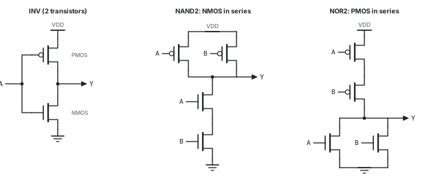
Area is quoted in gate equivalents (GE): one GE is a NAND2, which has four transistors. The values below are typical and are used for every estimate in this chapter.
| Cell | Transistors (static CMOS) | GE used here |
|---|---|---|
| INV | 2 | 0.67 |
| NAND2 | 4 | 1.00 |
| AND2 | 6 (NAND2 + INV) | 1.33 |
| OR2 | 6 (NOR2 + INV) | 1.33 |
| AND3 | 8 | 1.67 |
| OR3 | 8 | 1.67 |
| AND4 | 10 | 2.00 |
| XNOR2 | 8 to 12 | 2.33 |
| DFF | about 20 to 24 (transmission-gate master-slave) | 5.00 |
| DFFR | about 24 to 28 (with asynchronous reset) | 6.00 |
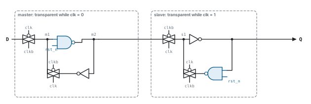
rst_n.How the flop works.
- While
clk= 0, the master’s input transmission gate is open, and node m1 follows D. The slave is closed and holds Q. - On the rising edge the master closes, holding m1, and the slave opens, passing the stored value to Q.
- Setup is the time D needs to get through the master’s gate and inverter before the edge.
- Clock-to-Q is the delay through the slave’s gate and inverter.
- Hold is the time D must stay stable while the master’s gate turns off.
Every flop’s clock pin drives four transmission gates, which is eight transistor gates, plus a local clock inverter. That is why flops dominate clock power (Section 5.3).
Asynchronous reset in silicon. Swapping two inverters for NAND2 gates adds about 4 transistors per flop. The NAND in the master’s forward path is slightly slower than an inverter, which adds to setup time. The rst_n wire has to reach every flop, and that makes a reset tree.
The four detectors for 1011, costed. The logic comes from minimized equations (for example the Mealy’s s0' = din; see F1). The flop counts are exact.
| Design | Flops | Flop GE | Logic GE | Total GE | Note |
|---|---|---|---|---|---|
| Mealy, binary | 2 | 12.0 | 7.3 | 19.3 | s1’ = s0 d’ + s1 s0’ d, s0’ = d, detect = s1 s0 d |
| Moore, binary | 3 | 18.0 | 11.0 | 29.0 | unused codes as don’t-cares, so detect = s2 for free |
| Moore, one-hot | 5 | 30.0 | 12.0 | 42.0 | no illegal-state recovery (about 8 GE more with it) |
| Shift + compare, fill counter | 5 | 27.0 | 8.7 | 35.7 | 3 history flops without reset + 2-bit fill counter |
| Shift + compare, reset trick | 3 | 18.0 | 2.7 | 20.7 | history resets to 000, so no counter is needed |
“In a small FSM, the flops are 60 to 70 percent of the area, so the area lever is the flop count, not the gates. That’s why binary encoding is the ASIC default, and why a one-hot costs about twice the area of the binary Mealy for 1011.”
5.2 Delay: logical effort
The delay of a gate, in units of τ (the delay of an ideal inverter driving an identical inverter, without parasitics), is
d = g · h + p
- g, the logical effort, says how much more input capacitance the gate presents than an inverter delivering the same current.
- h, the electrical effort or fan-out, is Cout / Cin.
- p is the parasitic delay from the gate’s own diffusion capacitance.
These values assume PMOS carries half the current of an equal-size NMOS (hole mobility is about half), so PMOS devices are drawn twice as wide.
| Gate | Logical effort g | Parasitic p | Why |
|---|---|---|---|
| INV | 1 | 1 | the reference |
| NANDn | (n + 2) / 3 | n | series NMOS; PMOS in parallel stay small |
| NORn | (2n + 1) / 3 | n | series PMOS must be n times wider: heavy inputs |
| NAND2 / NOR2 | 4/3 / 5/3 | 2 / 2 | this is why logic is built from NAND |
Stack limits. Every transistor added in series adds resistance, a charged internal node and body effect. Delay grows roughly with the square of the stack height, so libraries stop at NAND4 (and usually at NOR3).
Wide AND trees. The comparator in F6 to F8 ends in an N-input AND. For a 64-input AND driving a load 10 times its input capacitance (H = 10), logical effort gives:
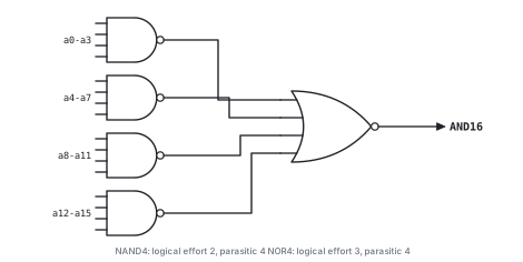
| 64-input AND built as | Stages | Path effort G | Stage effort f | Parasitic P | Delay D (τ) |
|---|---|---|---|---|---|
| NAND2 / NOR2 alternating | 6 | 11.0 | 2.19 | 12 | 25.1 |
| NAND4, NOR2, NAND4, NOR2 | 4 | 11.1 | 3.25 | 12 | 25.0 |
| NAND4, NOR4, NAND4, INV | 4 | 12.0 | 3.31 | 13 | 26.2 |
| NAND8, NOR8 | 2 | 18.9 | 13.74 | 16 | 43.5 |
The best trees use 4 to 6 stages, with a stage effort near 3 to 4, and take about 25 τ. Two giant gates take about 43 τ, even though they have fewer stages. That is why the pipelined compare in F8 splits the AND into slices of 8, where each slice is a two-stage NAND4/NOR2 tree.
Timing an FSM. The state loop must satisfy Tclk ≥ tclk-to-Q + tlogic + tsetup + margin. The 1011 Mealy has one AND-OR level of logic, about two gate delays, so it is nowhere near critical. A 64-state machine’s next-state logic could be 4 to 6 levels deep, and it cannot be pipelined (F21).
5.3 Power
P = α · C · V2 · f + Pshort-circuit + Pleakage
α is the activity factor: the probability that a node makes a 0-to-1 transition in a cycle. The clock has α = 1, and it drives every flop’s clock pin on every cycle whether or not D changes. So the flop count sets the clock-pin power: the 5-flop one-hot pays 2.5 times the clock power of the 2-flop Mealy.
Encoding and switching. Under random input, the Moore machine for 1011 spends 25% of its cycles in IDLE, 31.2% in S1, 25% in S10, 12.5% in S101 and 6.25% in S1011 (one hit per 16 bits, as expected). Weighting every arc by those probabilities gives the average number of state bits that toggle per cycle:
| Machine | Encoding | Flops | State-bit toggles per cycle |
|---|---|---|---|
| Moore | Binary (as in the RTL) | 3 | 1.06 |
| Moore | Gray along the forward path | 3 | 0.94 |
| Moore | One-hot | 5 | 1.44 |
| Mealy | Binary (as in the RTL) | 2 | 0.88 |
| Mealy | Gray along the forward path | 2 | 0.88 |
| Mealy | One-hot | 4 | 1.38 |
| Shift register | 3 history flops, random data | 3 | 1.50 |
What the table shows:
- Gray coding helps Moore a little (about 12% fewer toggles) and Mealy not at all, because the binary Mealy code is already Gray-like:
s0is just the previous bit. - One-hot toggles two bits on every state change, and it has the most flops.
- The shift register toggles the most, because every history flop follows the data.
Glitch power. Every spurious pulse charges and then discharges its node, costing about C V² in energy, and it repeats in every gate downstream (Figure 5.4). A Mealy output, or a wide binary decode, feeding a large fan-out can waste more power than the FSM itself uses.
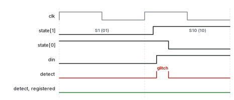
state moves from S1 (01) to S10 (10) while a new din = 1 arrives. state[1] rises before state[0] falls, so for a moment detect = state[1] & state[0] & din sees 1-1-1.Clock gating. An enable such as if (in_valid) can stop the clock instead of recirculating the data through a mux. A plain AND gate cannot do it safely: if the enable changes while the clock is high, the gated clock gets a runt pulse. The integrated clock gate (ICG) latches the enable while the clock is low, so the enable can only change the gate while the clock is low.
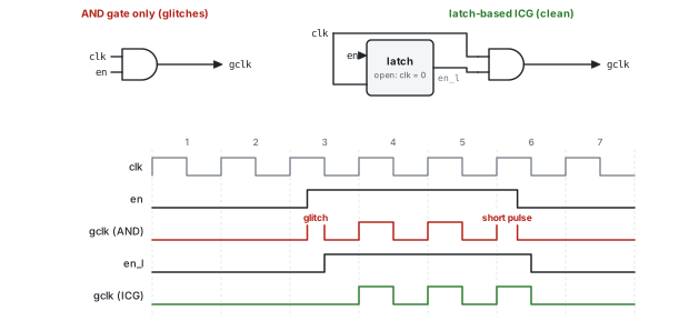
en changes while clk is high; the latch-based ICG does not.A gated bank saves its flops’ clock-pin power and the power of the clock tree beyond the ICG. Synthesis inserts ICGs automatically from enable conditions when the bank is wide enough, typically 3 or more flops. The shift-register detectors (F6, F8, F11) gain the most.
Leakage and threshold voltage. Subthreshold leakage scales with the total transistor width and grows exponentially as the threshold voltage drops. More flops therefore means more leakage, so a one-hot FSM or a long shift register leaks more. Detectors that are far from critical can use high-threshold cells: slower, but they leak much less.
Parallelism buys voltage. Doing W bits per clock (F12) at 1/W of the clock rate leaves time to spare, so the supply voltage can come down. With illustrative numbers:
- one serial detector at 0.9 V
- against W = 4 lanes with 4.4 times the switched capacitance, at 0.72 V and a quarter of the frequency
The dynamic power ratio is 0.57 / 0.81 = 0.70, about 30% less, paid for in area. This is the classic parallelism-for-power argument.
5.4 Reset at the circuit level

- Asynchronous reset lives inside the flop: the NAND gates of Figure 5.2. It works with no clock, costs about 4 transistors per flop, and needs a buffered reset tree to every flop. Its release has recovery and removal timing, like a data input, which is why it is synchronized (Section 1.5).
- Synchronous reset is an AND gate in the D path. It adds a gate to the setup path, although synthesis often merges it into the next-state logic. It needs a running clock while asserted, and it filters glitches on the reset line.
- Flops without reset are about 17% smaller in the GE model used here (5.0 versus 6.0), and each one takes a load off the reset tree. The fill counter of F6 is what makes that safe.
5.5 Metastability
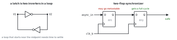
A latch has two stable points and one unstable balance point in between. If D changes inside the setup and hold window, the loop can start near the balance point. The voltage difference then grows as V(t) ≈ V0 · et/τ, where τ ≈ C / gm of the loop, so resolution takes time, and occasionally a long time. The standard model is:
MTBF = etr / τ / (T0 · fclk · fdata)
Here tr is the time allowed for resolution. The assumptions are τ = 20 ps, T0 = 20 ps, a 1 GHz clock and an asynchronous input toggling at 100 MHz.
| Synchronizer | Resolution time tr | MTBF |
|---|---|---|
| One flop, output used in the same cycle | 0.3 ns | about 1.6 seconds |
| Two flops | 1.1 ns | about 12 billion years |
The second flop adds 0.8 ns of resolution time, which multiplies the MTBF by e40, about 2 × 10¹⁷. In this topic it matters in three places: the debouncer’s input (F19), reset release (Section 1.5), and detect pulses that cross clock domains (F23).
5.6 The decision matrix
| Implementation | Flops for N bits | Logic | Critical path | Power | Flexibility | Use when |
|---|---|---|---|---|---|---|
| Binary Mealy FSM | ⌈log₂N⌉ | small, irregular | state loop; din→detect |
lowest | none | short fixed pattern, local consumer |
| Registered Mealy | ⌈log₂N⌉ + 1 | same | state loop only | low | none | output leaves the block |
| Binary Moore FSM | ⌈log₂(N+1)⌉ | small; decode | state loop | low | none | Moore timing, fewest flops |
| One-hot Moore | N + 1 | shallowest | shortest loop | more clock and leakage | none | FPGA, highest clock rate, glitch-free |
| Shift + compare | N − 1 (+ fill) | N-input AND | AND tree depth | data toggles every bit | any pattern, mask, multi-pattern | long, programmable or multiple patterns |
| Pipelined compare | N + N/8 | as above, split | one slice | as above | as above | very long patterns at high clock rates |
| Counter | ⌈log₂N⌉ | incrementer | carry chain | low | runs only | N identical bits, timeouts |
- “For a short fixed pattern, a binary FSM is the smallest: flops dominate the area and it has the fewest.”
- “An FSM is a feedback loop, so its speed is set by one clock-to-Q, the next-state logic and setup, and it can’t be pipelined. A comparator is feed-forward, so I can pipeline it.”
- “A Mealy output can glitch and couples two blocks’ timing budgets. At a boundary I register it.”
- “If the input has a valid, the enable becomes a clock gate, and the history flops stop burning clock power when idle.”
Appendix ARapid fire, mistakes, practice, glossary
A.1 Thirty rapid-fire follow-ups
Q1. How many flops does a Moore detector for a 10-bit pattern need? 11 states, so 4 binary flops, or 11 one-hot.
Q2. How many arcs does it have? Two per state: 22.
Q3. Can a Mealy output be glitch-free? Only by registering it, and then it has Moore timing.
Q4. Why does one-hot need fewer logic levels? Each flop’s input is the OR of its incoming arcs, each ANDed with din: two levels, and no decode.
Q5. What happens if every bit of a one-hot FSM becomes 0? Every next-state term is 0, so it locks up. A legality check recovers it.
Q6. Will synthesis keep your enum encoding? Not necessarily. Constrain it if it matters.
Q7. Where does an overlapping 1111 fire on 11111? At bits 4 and 5.
Q8. And a non-overlapping one on 11111111? At bits 4 and 8.
Q9. Is the prefix-rule FSM minimal? Yes. Every prefix state can be told apart from every other (F3).
Q10. Detect “at least three 1s in the last five bits”. A 5-bit window plus a popcount ≥ 3, the F10 structure. It’s not an FSM derivation.
Q11. With no counter, what should the history of a 0110 detector reset to? 111, the complement of the first bit.
Q12. Why not reset the history flops anyway? They are about 20% larger, add load to the reset tree, and the fill counter already masks them.
Q13. Synchronous or asynchronous reset? Either works: state your default. If it’s asynchronous, synchronize the release.
Q14. What limits the clock rate of a shift-register detector? The comparator’s AND tree, so pipeline it (F8).
Q15. What limits the clock rate of an FSM? The state loop, which cannot be pipelined.
Q16. What is the latency of the pipelined 64-bit detector? One cycle more than Mealy, the same as Moore.
Q17. How do you make an FSM’s pattern programmable? With a transition table in RAM, computed as a KMP table. It’s usually worse than a comparator (F7).
Q18. How do you find a pattern at any bit offset in a 32-bit word stream? 32 comparators over a window of 31 + N bits (F12).
Q19. What does a glitch cost in power? One charge and discharge of every node it reaches, repeated downstream.
Q20. Why does clock gating use a latch? The latch holds the enable steady while the clock is high, so no runt pulses reach the gated clock.
Q21. What is a border? The longest proper prefix of the pattern that is also a suffix.
Q22. en low should break the sequence, not pause it. What changes? Go to IDLE whenever en is low, instead of holding the state (F11).
Q23. Detector versus comparator: what is the difference? A comparator matches a word presented all at once. A detector matches across time, so it needs memory.
Q24. Which stream proves the overlap arc is right? 1011011: an overlapping detector must fire twice.
Q25. Where does `timescale go? In every file, or in none.
Q26. What is $onehot0 good for here? Tolerating one bit error (F10), and checking that a one-hot state is legal.
Q27. You need 1011 and 1010 merged. How many states? Four: “”, 1, 10 and 101. S101 outputs A on a 1 and B on a 0.
Q28. How many flops does divisible-by-7 need? Three.
Q29. What does your RTL do if din is X in simulation? A ?: with an X select merges both operands, so the state goes X. Drive known values, and assert !$isunknown(din) on valid cycles.
Q30. What single change most improves a Mealy detector at a block boundary? Register its output.
A.2 Mistakes that cost offers
- Sending every mismatch back to
IDLE. It passes1011but misses101011and11011. - Forgetting the outgoing arcs of the Moore detect state.
- Implementing non-overlap as “reset on every mismatch”.
- Never asking which bit arrives first.
- Letting a Mealy output drive another block or clock domain directly.
- Building a shift-register detector that fires falsely after reset.
- Leaving a path in
always_combunassigned, which infers a latch. - Using blocking assignments in
always_ff. - Using
unique casewithout full coverage. - Using a two-flop synchronizer on a serial data stream.
- Sizing a counter that must reach N with
$clog2(N)bits. - Writing the golden model by copying the RTL, so both are wrong the same way.
A.3 Practice problems, with answers
P1. Derive the Mealy and Moore tables for 1101 and 1001 (overlapping), then dry-run 1101101 and 1001001.
Answer: The Mealy tables are in Section 2.5. The extra Moore states are:
S1101: 0 →IDLE, 1 →S11S1001: 0 →S10, 1 →S1
Both streams fire at bits 4 and 7 when overlapping, and only at bit 4 when non-overlapping.
P2. Make the one-hot Moore machine non-overlapping by moving one term.
Answer: Move ~din & st[S1011] from S10’s equation into IDLE’s. That is exactly what the OVERLAP terms in Listing 3.9 do.
P3. Draw the divisible-by-3 FSM for an MSB-first stream. Answer: See Figure 3.12. The rule is r → (2r + b) mod 3.
P4. Why does a shift register whose history resets to 000 never fire falsely for 1011, but does for 0011?
Answer: A match of 1011 needs the oldest window bit to be 1, and that bit stays a reset 0 until three real bits have arrived. The pattern 0011 starts with two 0s, which the reset value can supply.
P5. Sketch seq_det_shift for 4 bits per clock.
Answer: Listing 3.7: a 7-bit window and 4 comparators.
P6. Design an overlapping Moore detector for 110. How many states does it need?
Answer: Four: IDLE, S1, S11 and S110. S110 goes to IDLE on a 0 and S1 on a 1. The pattern has no border, so the non-overlapping machine is identical.
P7. A 16-bit sync word must be found with at most one bit error. Which structure do you use?
Answer: A shift register plus $onehot0(window ^ pattern). It needs about 2N gates and no popcount.
P8. How many register bits does seq_det_prog need for NMAX = 32?
Answer: 31 history flops and 5 fill flops inside the module. The pattern, care and len registers add 32 + 32 + 6 = 70 bits outside it, so about 106 in total.
A.4 Glossary
Activity factor (α): the probability that a node switches 0 to 1 in a cycle.
Aho–Corasick: an automaton that matches several patterns at once (F9).
Border: the longest proper prefix of a pattern that is also a suffix.
Clock-to-Q: the delay from a clock edge to the flop’s output changing.
Equivalent states: states with the same outputs whose next states are also equivalent; they can be merged.
Fill counter: counts real history bits, so a shift-register detector cannot fire on stale data.
Gate equivalent (GE): the area of one NAND2.
Glitch: a spurious pulse caused by unequal path delays.
Gray code: an encoding where successive codes differ in one bit.
Hold time: how long D must stay stable after the clock edge.
ICG: integrated clock gate: a latch plus an AND gate.
KMP: the Knuth–Morris–Pratt matching algorithm; its automaton is the prefix-rule FSM.
Logical effort (g): a gate’s input capacitance relative to an inverter delivering the same current.
Mealy machine: outputs depend on the state and the inputs.
Metastability: a latch stuck near its balance point after a timing violation.
Moore machine: outputs depend only on the state.
MTBF: the mean time between synchronizer failures.
One-hot: one flop per state, with exactly one set at a time.
Output-encoded state: an encoding where an output is simply one state bit.
Overlapping detection: matches may share bits.
Recovery and removal: the setup and hold requirements for releasing an asynchronous reset.
Registered Mealy: a Mealy output with a flop on it; Moore timing, glitch-free.
Setup time: how long D must be stable before the clock edge.
Transmission gate: a parallel NMOS and PMOS pair used as a switch.
A.5 References
- D. E. Knuth, J. H. Morris, V. R. Pratt, “Fast Pattern Matching in Strings,” SIAM Journal on Computing, 6(2), 1977.
- A. V. Aho, M. J. Corasick, “Efficient String Matching: An Aid to Bibliographic Search,” Communications of the ACM, 18(6), 1975.
- N. H. E. Weste, D. M. Harris, CMOS VLSI Design: A Circuits and Systems Perspective, 4th ed., Addison-Wesley, 2010.
- I. Sutherland, B. Sproull, D. Harris, Logical Effort: Designing Fast CMOS Circuits, Morgan Kaufmann, 1999.
- A. P. Chandrakasan, S. Sheng, R. W. Brodersen, “Low-Power CMOS Digital Design,” IEEE Journal of Solid-State Circuits, 27(4), 1992.
- C. E. Cummings, “Coding and Scripting Techniques for FSM Designs with Synthesis-Optimized, Glitch-Free Outputs,” SNUG Boston, 2000.
- C. E. Cummings, D. Mills, “Synchronous Resets? Asynchronous Resets? I Am So Confused! How Will I Ever Know Which to Use?” SNUG San Jose, 2002.
- C. E. Cummings, D. Mills, S. Golson, “Asynchronous & Synchronous Reset Design Techniques, Part Deux,” SNUG Boston, 2003.
- C. E. Cummings, “Clock Domain Crossing (CDC) Design & Verification Techniques Using SystemVerilog,” SNUG Boston, 2008.
- IEEE Std 1800-2017, IEEE Standard for SystemVerilog: Unified Hardware Design, Specification, and Verification Language.